Your Ultimate Amplifier PCB Manufacturer
Your Ultimate Amplifier PCB Manufacturer
SMTFAB is a top amplifier PCB supplier and factory in China. We can provide innovative, excellent, and reliable PCB solutions for your next project.
- More than ten years Amplifier PCB manufacturing experience
- Provide a One-stop solution for your requirement
- Customize design amplifier circuit board
- Fast delivery time even in peak season
SMTFAB - Reliable Amplifier PCB Manufacturer
If you need an expert amplifier PCB supplier in China, SMTFAB is your to-go choice. We manufacture amplifier PCBs suitable for your project needs. If you require a special amplifier PCB, you can send us your design. From prototype to mass production, we provide full support on your product development.
Kindly send us your layout, we will ensure to satisfy your specific requirement.
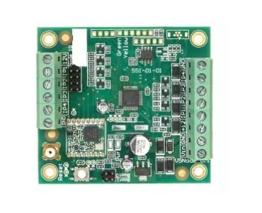
Types of Amplifier PCB Meet Your Requirements

500W amplifier PCB is a robust build-based and circuit-designed MOSFET. The base materials used are CEM3, FR-4, FR1, and TG130. Solder masks can be white, black, blue, green, yellow, and red.

The class H amplifier PCB has a copper thickness of 10Z. It’s min. Line width is 0.075mm and 1.5mm board thickness. The base material of this PCB is FR4.

The 600W amplifier PCB is popular using transistor 2SC5200. It comes in different surface finishing, either immersion gold, HASL, and OSP. The 600W amplifier printed circuit board with high power uses has an impedance of 4 Ohm.

This 400W mono amplifier PCB use best for stereo subwoofers and power transistors for home. It has vast power supply support and ultra-low distortion. It is applicable in the military, medical, automotive, and LED industries.

The 300W amplifier PCB has FR4 base material. The max size of the board is 1190mm x 350mm. The primary voltage is 230V/60Hz. It is perfect for flying probe tester, electrical testing, x-ray, and functional test.

94v0 power amplifier PCB available in a different assembly. It can be SMT, mixed, through-hole, and BGA. It is 100% E-testing services and performs flying-probe PCB tests.
Why Choose SMTFAB for Your Amplifier PCB
As a premier amplifier PCB manufacturer, SMTFAB has an advanced production line to manufacture products. We can offer complete service, manufacture, and assembly of your product. We import all of our machinery from the USA and Europe.
SMTFAB implements a strict quality system to ensure your amplifier PCB quality. We have an experienced engineering and technical team to send your timely and professional PCB solution. Contact us support team now.

Related Amplifier PCB Boards


Amplifier PCB Production Details As Following Up
- Production Facility
- PCB Capabilities
- PCB Materials
- Shipping Methods
- Payment Methods
- Send Us Inquiry


| Item | Capability |
| Layer Count | 1-40layers |
| Base Material | KB、Shengyi、ShengyiSF305、FR408、FR408HR、IS410、FR406、GETEK、370HR、IT180A、Rogers4350B、Rogers4000、PTFE Laminates(Rogers series、Taconic series、Arlon series、Nelco series)、Rogers/Taconic/Arlon/Nelco laminate with FR-4 material(including partial Ro4350B hybrid laminating with FR-4) |
| Board Type | Backplane、HDI、High multi-layer 、blind&buried PCB、Embedded Capacitance、Embedded resistance board 、Heavy copper power PCB、Backdrill. |
| Board Thickness | 0.2-5.0mm |
| Copper Thickness | Min. 1/2 OZ, Max. 10 OZ |
| PTH Wall | 25um(1mil) |
| Maximum Board Size | 1100*500mm(43”*19”) |
| Min laser drilling size | 4mil |
| Min. Spacing/Tracing | 2.7mil/2.7mil |
| Solder Mask | Green, Black, Blue, Red, White, Yellow,Purple matte/glossy |
| Surface Treatment | Flash gold(electroplated gold)、ENIG、Hard gold、Flash gold、HASL Lead free、OSP、ENEPIG、Soft gold、Immersion silver、Immersion Tin、ENIG+OSP,ENIG+Gold finger,Flash gold(electroplated gold)+Gold finger,Immersion silver+Gold finger,Immersion Tin+Gold finger. |
| Min. Annular Ring | 3mil |
| Aspect ratio | 10:1(HASL Lead free、HASL Lead、ENIG、Immersion Tin、Immersion silver、ENEPIG);8:1(OSP) |
| Impedance control | ±5ohm(<50ohm), ±10%(≥50ohm) |
| Other Techniques | Blind/Buried Via |
| Gold Fingers | |
| Press Fit | |
| Via in Pad | |
| Electrical Test |
Here there’re many laminate material datasheets, they’re useful and helpful for you, please see them:
| SUPPLIER | PCB LAMINATE | TYPE | MATERIAL DATASHEET | TG | TD | DK(1MHZ) | DK(1GHZ) | DK(10GHZ) |
| KB | KB-6160 | FR4 | DOWNLOAD | 135 | 305 | 4.35 | – | – |
| KB-6160A | FR4 | DOWNLOAD | 135 | 305 | 4.35 | – | – | |
| KB-6160C | FR4 | DOWNLOAD | 135 | 314 | 4.7 | – | – | |
| KB-6150 KB-6150C | FR4 | DOWNLOAD | 132 | 305 | 4.6 | – | – | |
| KB-6164 | FR4 | DOWNLOAD | 142 | 330 | 4.8 | – | – | |
| KB-6164F | FR4 | DOWNLOAD | 145 | 340 | 4.8 | – | – | |
| KB-6165F | FR4 | DOWNLOAD | 150 | 346 | 4.8 | – | – | |
| KB-6167F | FR4 | DOWNLOAD | 170 | 349 | 4.8 | – | – | |
| SHENGYI | S1141 | FR4 | DOWNLOAD | 135 | 310 | 4.6 | – | – |
| S1141KF | FR4 | DOWNLOAD | 140 | 350 | 4.7 | – | – | |
| S1000 | FR4 | DOWNLOAD | 155 | 335 | 4.9 | – | – | |
| S1170 | FR4 | DOWNLOAD | 170 | 335 | 4.6 | – | – | |
| S1000-2 | FR4 | DOWNLOAD | 170 | 335 | 4.8 | – | – | |
| S1155 | FR4 | DOWNLOAD | 135 | 370 | 4.7 | – | – | |
| ITEQ | IT-158 | FR4 | DOWNLOAD | 150 | 340 | 4.6-4.8 | – | – |
| IT-180 | FR4 | DOWNLOAD | 180 | 350 | 4.5-4.7 | – | – | |
| TUC | TU-768 | FR4 | DOWNLOAD | 180 | 350 | – | 4.3-4.4 | 4.3 |
| TU-872 | Modified Epoxy | DOWNLOAD | 200 | 340 | – | 3.8-4.0 | 3.8 | |
| ROGERS | RO 3003 | Cer/PTFE | DOWNLOAD | – | 500 | – | – | 3 |
| RO 3010 | Cer/PTFE | DOWNLOAD | – | 500 | – | – | 10.2 | |
| RO 4003 | Hydrocarbon/Cer | DOWNLOAD | >280 | 425 | – | – | 3.38 | |
| RO 4350B | Hydrocarbon/Cer | DOWNLOAD | >280 | 390 | – | – | 3.48 | |
| RT/duroid 5880 | PTFE/Glass | DOWNLOAD | – | 500 | – | – | 2.2 | |
| ISOLA | Polyclad 370HR | FR4 | DOWNLOAD | 170 | 340 | 4.8-5.1 | – | – |
| FR406-HR | FR4 | DOWNLOAD | 190 | 325 | 3.91 | 3.86 | 3.81 | |
| FR408-HR | FR4 | DOWNLOAD | 200 | 360 | 3.72 | 3.69 | 3.65 | |
| P96 | Polyimide | DOWNLOAD | 260 | 416 | – | 3.78 | 3.73 | |
| Hitachi | MCL-BE- 67G | Modified Epoxy | DOWNLOAD | 140 | 340 | 4.9 | 4.4 | – |
| MCL-E-679F | FR4 | DOWNLOAD | 170 | 350 | 4.2-4.4 | 4.3-4.5 | – | |
| MCL-LX-67Y | Special Laminate | DOWNLOAD | 185-195 | 325-345 | – | 3.4-3.6 | – | |
| Nelco | N4000-13 | Modified Epoxy | DOWNLOAD | 210-240 | 365 | – | 3.7 | 3.6 |
| N4000-13EP | Modified Epoxy | DOWNLOAD | 210-240 | 350 | – | 3.4 | 3.2 | |
| N4000-13SI | Modified Epoxy | DOWNLOAD | 210-240 | 350 | – | 3.4 | 3.2 | |
| N4000-13EP SI | Modified Epoxy | DOWNLOAD | 210-240 | 350 | – | 3.4 | 3.2 | |
| Taconic | TLX-6 | PTFE | DOWNLOAD | – | – | – | – | 2.65 |
| TLX-7 | PTFE | DOWNLOAD | – | – | – | – | 2.6 | |
| TLX-8 | PTFE | DOWNLOAD | – | – | – | – | 2.55 | |
| TLX-9 | PTFE | DOWNLOAD | – | – | – | – | 2.45 | |
| RF35 | PTFE | DOWNLOAD | <315 | – | 3.5 | – | 3.5 | |
| TLC-27 | PTFE | DOWNLOAD | – | – | – | – | 2.75 | |
| TLC-30 | PTFE | DOWNLOAD | – | – | – | – | 3 | |
| TLC-32 | PTFE | DOWNLOAD | – | – | – | – | 3.2 | |
| Arlon | Arlon 25N | Cer | DOWNLOAD | 260 | – | – | – | 3.38 |
| Arlon 25FR | Cer | DOWNLOAD | 260 | – | – | – | 3.58 | |
| Arlon 33N | Polymide | DOWNLOAD | >250 | 353 | 4 | – | – | |
| Arlon 35N | Polymide | DOWNLOAD | >250 | 363 | 4.2 | – | – | |
| Arlon 85N | Polymide | DOWNLOAD | 250 | 387 | 4.2 | – | – | |
| Stablcor | ST325 | – | DOWNLOAD | Thermal conductivity:75w/m.k(with 1oz copper) | ||||
| ST10 | – | DOWNLOAD | Thermal conductivity:325w/m.k(with 1oz copper) | |||||
| Panasonic | R-1566W | FR4 | DOWNLOAD | 140 | 330 | 4.95 | 4.7 | 4.65 |
| Ventec | VT-901 | Polymide | DOWNLOAD | 250 | 390 | 4.2-4.5 | 4.0-4.3 | – |
| VT-90H | Polymide | DOWNLOAD | 250 | 390 | 4.2-4.5 | 4.0-4.3 | – | |
| Bergquist | ht-04503 | – | DOWNLOAD | Thermal conductivity:2.2w/m.k(with 1oz copper) | ||||
Delivery
SMTFAB offers flexible shipping methods for our customers, you may choose from one of the methods below.
1. DHL
DHL offers international express services in over 220 countries.
DHL partners with SMTFAB and offers very competitive rates to customers of SMTFAB.
It normally takes 3-7 business days for the package to be delivered around the world.

2. UPS
UPS gets the facts and figures about the world’s largest package delivery company and one of the leading global providers of specialized transportation and logistics services.
It normally takes 3-7 business days to deliver a package to most of the addresses in the world.

3. TNT
TNT has 56,000 employees in 61 countries.
It takes 4-9 business days to deliver the packages to the hands
of our customers.

4. FedEx
FedEx offers delivery solutions for customers around the world.
It takes 4-7 business days to deliver the packages to the hands
of our customers.

5. Air, Sea/Air, and Sea
If your order is of large volume with SMTFAB, you can also choose
to ship via air, sea/air combined, and sea when necessary.
Please contact your sales representative for shipping solutions.
Note: if you need others, please contact your sales representative for shipping solutions.
On our website you can use the following payment methods:
Telegraphic Transfer(TT): A telegraphic transfer (TT) is an electronic method of transferring funds utilized primarily for overseas wire transactions. It’s very convenient to transfer.
Bank/Wire transfer: To pay by wire transfer using your bank account, you need to visit your nearest bank branch with the wire transfer information. Your payment will be completed 3-5 business days after you have finished the money transfer.
Paypal: Pay easily, fast and secure with PayPal. many other credit and debit cards via PayPal.
Credit Card: You can pay with credit card: Visa, Visa Electron, MasterCard, Maestro.
[contact-form-7 id=”764″ title=”Quick Quote”]
Your Expert Amplifier PCB Supplier
SMTFAB is a professional PCB manufacturer who can offer you the highest quality amplifier PCB. We have a world-class manufacturing system and service capabilities that will benefit your business.
As an expert supplier, SMTFAB manufacture and supply amplifier PCB widely applied in electrical appliances, consumer electronic products, small household electrical appliances, and medical equipment. You can also find this component in TV, mobile phone, telephone, computer products, and more.
SMTFAB amplifier PCB is available in various surface finish, designs, dimensions, styles, and materials. Along with it are the PCB layer(s), laminate thickness, and other technical requirements. If ever you are unsure which product suits your project, you can contact us; we will be delighted to assist you and advise.
Furthermore, SMTFAB can customize the amplifier circuit board according to your requirements. We can tailor the speed, dispatch, components, numbers of soldering pads, and other specs upon request. You can send us the file and get an instant quote.
If you choose the purchase PCB at SMTFAB, you can get suitable quality components. All amplifier PCBs are 100% tested. Implementing an ISO9001 quality system, we can guarantee high-quality PCB products.

SMTFAB series of amplifier PCB is highly reliable. Competitive in price; best cost performance. Regardless of your project requirements, we can provide a fast prototype service.
SMTFAB will provide you with all the knowledge you need to make the best choice. Including the essential things to consider like power, dynamics, range, etc. With over 15 years of experience in the field, we have proven our commitment to delivering quality products and services.
To meet evolving customers’ needs, we engross to deliver a comprehensive variety of amplifier PCB. Please email us at sales@SMTFAB.com or call us at +86-755-23196857 so we can talk about your business.
We are looking forward to working with you.
Amplifier PCB: The Ultimate FAQ Guide
Amplifier PCBs are one of the most important types of PCB, which the PCB industry is producing on a large scale. The PCB industry is getting many benefits from it.
They have many applications in different fields like telecommunication, radar systems, engine systems, space industry, satellites systems, and electrical equipment industry.
If you have any query and you want to know about our product i-e Amplifier PCB. You are at the right place and have access to authentic information about our reliable product.
- What is an Amplifier PCB?
- What is the Main Objective of Amplifier PCB?
- On What Principle Does an Amplifier PCB Works?
- What are the Different Types of Amplifier PCB?
- What are the Applications of Amplifier PCB?
- What are the Different Components of Amplifier PCB, and What You Should Consider While choosing them?
- What is the Stability of an Amplifier PCB?
- What is the Standard Layout or Design Considerations of the Amplifier PCB?
- What are the Different Benefits of Amplifier PCB?
- What Material is Best for Amplifier PCB?
- How can You Improve the Performance of an Amplifier PCB?
- How many Layers does an Amplifier PCB have?
- What is the Difference between a Simple PCB and an Amplifier PCB?
- What is the Concept of Stray Capacitance in an Amplifier PCB Layout?
- What are the Functions of Heat Sinks in an Amplifier PCB?
- What is the Fabrication of an Amplifier PCB?
- How Does an Amplifier PCB Control Excess Heat?
- What are the Quality Measures for an Amplifier PCB?
- From where you can buy an Amplifier PCB?
What is an Amplifier PCB?
An amplifier printed circuit board is the part of the amplifier that receives a signal and interprets it.
Generally, when the amplifier printed circuit boards receive a low-level stereo signal, it amplifies it.
Amplifier circuit board, when receives a signal it passes through the transistor, the integrated chip that is also known as IC chip.
After that, it passes through a tube that adds more current to it from a power supply.
They are known as voltage amplifiers because they amplify a low voltage signal into a high voltage signal.
Their frequency ranges from 18Hz to 25 kHz. In addition, they convert these signals very efficiently.
You can use these amplifier circuit boards in the devices of wireless communications and broadcasting systems.
They have a lot of other applications and benefits.
They are different types of amplifier PCB present.

A simple amplifier PCB
What is the Main Objective of Amplifier PCB?
An amplifier PCB is a complex type of printed circuit board that converts low voltage signals into higher voltage signals using different components.
These amplifiers’ PCB increases the voltage of the signals, and the resultant power coming out of the signal increases.
There are many components of it like resistors, capacitors, and many important parts.
Heat sinks are also present in the amplifier PCBs to help the circuit release its heat and let it cool.
They are also present in stereo systems, hearing aid, and telephone receivers.
They have vast usage in different complex devices.
An amplifier PCB shape and size can vary according to the requirement of the device in which you are installing it.
The designing of a good amplifier PCB is critical. Any fault or flaw in its making can lead to leakage resistance, voltage drift, or stray capacitance during its processing.

The main objective of an amplifier PCB
On What Principle Does an Amplifier PCB Works?
Amplifier PCB works on the principle that it produces the out signal that is exactly like the input signal but with its magnitude increased.
The principle of the Amplifier circuit board also includes converting direct current (DC) from the power supply to output alternating current (AC).
The working principle is very important for the efficient working of the amplifier PCB.
There are many components on the amplifier board, which helps ensure the proper function and working of the amplifier printed circuit board.
The amplifier PCB is the board whose making is of fiberglass along with the plastic resin.
Make an etching or the paths on it that are conductive. Place different components of PCB on it.
Many other components like resistors, capacitors, and amplifying tubes are present that helps in the conductivity of the amplifier PCB. It prevents issues like stray capacitance and voltage drift.
The frequency range and capacity of each amplifier circuit boar depend on its size. Moreover, it also depends on its use in the type of device.

The principle of an amplifier PCB
What are the Different Types of Amplifier PCB?
There are many types of amplifier PCB depending upon its functionality and design or layout.
This type of classification is done based on the designing of the amplifier circuit board while processing it.
These are as follows:
PCB type A
PCB type B
PCB type C
Amplifier PCB type A:
It is highly linear and can be drawn graphically as a linear line.
The angle of conduction is three-sixty (360) degrees.
The mechanism is just like other amplifiers PCBs. The processing of a signal input results in an output signal with increased magnitude.
Amplifier PCB type B:
It is of great importance. The activity of this amplifier PCB includes two devices.
When the signal coming is in the positive and negative cycles known as alternating current. Therefore, it is best to do the biasing of different amplifier PCBs.
Two types of signals coming from both sides result in the output signal. It is a very critical type of amplifier circuit board.
Amplifier PCB type C:
It has its importance. The angle of conduction in the case of type C amplifier PCB is 180 degrees.
It has two types of modes of working
turned mode
an unturned mode.
These two mechanisms play a major role in their proper functioning.
The efficiency of this type of amplifier PCB is no more than 60 to 70 percent.

Type of the amplifier PCB
What are the Applications of Amplifier PCB?
There are many applications of an amplifier printed circuit board.
The most important feature is the converting of a low-level signal into a signal of high magnitude.
It is the first and important feature.
However, the applications include:
Usage of an amplifier PCB in the wireless communication devices and number of sensors.
It has applications in the voltage and current regulations.
Apart from that, it has its uses in the systems of electrical protections
They are present in different audio amplifiers and other alarm systems.
It has applications in broadcasting systems and telecommunications. They amplify the signal that passes through them.
They also have been used in portable audio amplifiers.
It has its uses in engines and other systems.
They also have used motors and digital converters.
They also have applications in radar systems and the space industry.

The applications of an amplifier PCB
What are the Different Components of Amplifier PCB, and What You Should Consider While choosing them?
There are different components for making an amplifier PCB.
These include a board that is made of plastic resin along with fiberglass of high quality. The boards have transistors, capacitors, and diodes.
Place these components in such a way as to avoid any stray capacitance and any voltage drift.
There are many factors that you should consider while choosing components for your amplifier PCB.
To have a successful amplifier PCB, you need to have a board design. That is including all of the major components.
For the quick and accurate placing of the components, use wires on the design board of the amplifier PCB.
The soldering of different components on this board is very important. This step needs precision.
Keep in mind these things before you start laying out your amplifier PCB
The availability of the components for amplifier PCB
The cost of the components
Their thermal tolerance
The chemical resistance
Mechanical stability of the components.
What is the Stability of an Amplifier PCB?
It is very critical when it comes to the maintenance of amplifier PCB stability.
Many factors are there that can disrupt the normal working and stability of the amplifier PCB.
One of them is thermal heat. It can directly affect the working of the amplifier PCB. Therefore, it is great to have a system that controls heat.
For this purpose, the amplifier PCB designers introduce heat sinks in the circuit boards.
These heat sinks would help in the dissipation of heat that revolves around the circuit.
It would reduce the risk of amplifier PCB failure.
There is a suggestion for you that make heat sinks of thicker material since thicker material dissipates heat better than thin material.
There are many types of heat sinks. However, the best heat sink is an aluminum heat sink.
It dissipates heat efficiently compared to other types of heat sinks.
In addition, you can also use linear conduction through copper surfaces to dissipate heat.
Apart from this, staggered micro vias also work well in the stability of an amplifier PCB.

The graph showing the stability of an amplifier PCB
What is the Standard Layout or Design Considerations of the Amplifier PCB?
The designing and layout of an amplifier PCB are as critical as any other step related to it.
The designer of the amplifier PCB needs to keep many things in mind that can prevent many problems.
Before you start placing components on the board, the first thing you should consider is the size of the board.
The size will indicate the number of components it can fit in.
After this, make sure you have a plan. That where and how many components you must place on the board.
It would make the mounting of the components easy.
Moreover, you need to consider the number of layers you have to use in your amplifier PCB. It would be according to the requirement of the device in which the amplifier PCB is going to use.
There should be enough spacing between different components of an amplifier PCB to prevent overheating and short-circuiting.
Place heat sinks for the components that produce excessive heat.

The design of an amplifier PCB
What are the Different Benefits of Amplifier PCB?
There are many benefits of the amplifier PCB.
The first and foremost benefit is the conversion of a low-frequency signal into a high-frequency signal with increased magnitude.
In simple printed circuit boards, there are chances of technical faults. However, an amplifier PCB has a mechanism to prevent any casualties.
They also have made role in signal integrity.
One other benefit of the amplifier PCB is its vast application in different high-tech devices.
This amplifier PCB has applications in telecommunication services, wireless communication systems, and radar systems.
They have wide use in engine rooms.
You can also use them in portable audio systems.
The space industry, electrical equipment industry, and satellite systems use them.
Many more benefits of an amplifier PCB are there that you can obtain by accurate handling of an amplifier PCB.
Make sure there is no flaw in the design of the amplifier PCB.
What Material is Best for Amplifier PCB?
The selection of the best material for the manufacturing of an amplifier PCB is crucial.
It can lead you to either successful manufacturing or a complete failure.
So select a material that will bring on a minimum or zero number of issues.
The best type of material that you can use is FR4.
Its capability of resistance to heat shock, corrosion, and damage makes it the best of its type.
There are many types of materials used in the manufacturing of amplifier PCB. These materials range from F1 to G10.
These materials include alumina, PTFE, and Kapton.
While you select material for your amplifier PCB, you need to make sure that it has thermal tolerance, resistance to corrosion, or any other type of physical or environmental damage.
You may also use thermoset dielectric materials for your amplifier PCB.

The material for an amplifier PCB
How can You Improve the Performance of an Amplifier PCB?
Many ways are present through which you increase the performance of an amplifier PCB.
There must be an increase in the stability of your amplifier PCB.
The greater the stability, the greater is the performance of the amplifier PCB.
The first thing that can increase the stability and performance of amplifier PCB is placing the heat sinks.
They can reduce the risks of overheating and ultimately damaging the functioning of amplifier PCB.
Moreover, you must consider installing ground planes to be away from the input pins.
If they are close to each other, it can increase the stray capacitance, voltage drift, and ground noise of the circuit.
Therefore, you must avoid close placement of these two.
Apart from that, the use of a bypass capacitor can increase the performance of amplifier PCB.
It is advised that you must place the bypass capacitor close to the amplifying pins, unlike ground planes.
The close placement of the bypass capacitor will help reduce the noise that your circuit is producing.
This type of layout will also help in reducing the chances of distortion or any other interference.
How Many Layers does an Amplifier PCB have?
No restriction is present on the number of layers that you can use for an amplifier PCB.
It depends on the requirements of the operating devices. You can always select any number for the layers.
Usually, there are single-layer PCB, double-layer PCB, and Multilayer PCB.
It is a low-frequency circuit board. They are not the best types of amplifier boards.
They are high chances that a single-layer amplifier PCB has noise production.
You can use them in low-technology electronics. It is not suitable for high-tech electronics.
You can use thin cladding of copper in designing them.
You can use the double-layer amplifier PCBs in devices that have a bit of complexity in them.
They consist of two foils.
These foils make it easy to route them.
Route the signals in the top layer of the double-layer amplifier PCB.
What is the Difference between a Simple PCB and an Amplifier PCB?
There are many differences between a simple printed circuit board and an amplifier printed circuit board.
You can design a simple printed circuit board through a photomask manually.
In this method, you need to place a photomask on the transparent sheet and obtain the prints/traces through the adhesion tape.
On the contrary, the amplifier PCB is of higher quality and uses advanced methods and software for its design.
When you are placing components on the board, in the case of the simple printed circuit board, a technology known as a through-hole is used.
Whereas, in the case of amplifier PCB, you can place components on the circuit board through special software known as (Easy EDA).
However, the type of operating device decides the thickness of the amplifier PCB board, its size, and dimensions.
The amplifier PCB is of higher quality as compared to the simple printed circuit board.
What is the Concept of Stray Capacitance in an Amplifier PCB Layout?
By stray capacitance, it means that there is an unwanted and undesired capacitance present in the circuit.
It happens due to the close placement of the components of the amplifier PCB. Moreover, the parallel alignment and exposure to the environment can cause it too.
Stray capacitance can also lead to stray inductance.
All these factors can cause resonating circuits.
You can avoid the stray capacitance by the accurate placement of the components of the amplifier PCB.
You can also prevent stray capacitance by using a bypass capacitor in your amplifier PCB circuit.
It also prevents any distortion or interference in the circuit.
In addition, if you place components of amplifier PCB at enough distance, you can avoid any stray capacitance present in the circuit.

The stray capacitance of an amplifier PCB
What are the Functions of Heat Sinks in an Amplifier PCB?
Heat sinks are the passive heat exchangers present in the circuit that transfer the heat energy present in the circuit away from the device.
You can install heat sinks in the amplifier PCB to get rid of heat present in the circuit.
Heat production is present in the circuit when the placement of the components is close to each other.
You can use the medium as a heat sink, where you can transfer the heat is usually air or liquid medium.
You can use many types of materials for the manufacturing of heat sinks. However, the best material you can use is aluminum due to its high conductivity.
Many other properties of aluminum make it best for heat sinks. These are its ability to prevent any chemical corrosion attacks, heat resistance, and other damages.
Some heat sinks come with already present tapes. Due to this, you can save time for installing it.

The schematic view of the heat sink of an amplifier PCB
What is the Fabrication of an Amplifier PCB?
The fabrication of an amplifier PCB process is a very critical stage.
The fabrication process is before the assembly of the PCB board.
In this process, many steps are present that involves marking, punching, drilling, plating, and mounting.
The start of the amplifier PCB fabrication process is by making a scheme of the circuit.
You need to draw a sketch where you can see which components you are placing on the board.
Use software to design the amplifier PCB.
This schematic or sketch will function as a blueprint of the fabrication process.
The fabrication process must consider:
You must obtain an output power supply by calculating the voltage of the amplifier.
The performance of components and their stability.
Capacitors, resistors, and diodes.
A heat sink must be present to remove all excessive heat present in the circuit.
Select all the raw materials that are best for the fabrication of amplifier PCB.
Etch marks and drill holes in the amplifier PCB.
When you complete all the fabrication processes, make sure your amplifier circuit board works properly.

The fabrication of an amplifier PCB
How Does an Amplifier PCB Control Excess Heat?
Design the amplifier PCB in such a way that it has mechanisms to control excess heat production in the circuit.
The production of heat in the circuit takes place when you place the components parallel to each other or close to each other.
The most important mechanism that controls and dissipates excess heat is the installation of the heat sinks.
You must install them near the components that produce excessive heat.
Heat sinks are of different shapes and sizes. Their sizes depend on the amount of heat energy that is required to remove from the circuit.
Some heat sinks come with tapes for easy installation.
What are the Quality Measures for an Amplifier PCB?
Many quality tests are present that you can perform to make sure the quality of the amplifier circuit board.
The necessary tests that you can perform to test the amplifier PCB are grid testing and ATG testing.
You can use these two tests to check the following aspects of the amplifier printed circuit board, these are:
You must make sure that there is very little loss of energy through dissipation. There must be minimal loss of output signal.
It must maintain its dielectric constant that is going to variate in case of excessive heat.
From where you can buy an Amplifier PCB?
SMTFAB is a trustworthy and professional PCB producer, they have a factory in china, and warehouses in many countries.
You can order your PCBs from this best and high-quality amplifier PCB manufacturer.
SMTFAB is highly trustworthy and an extensive PCB company.
They have been in the PCB industry since 2008.
They are giving their best services in more than 60 countries.
You must consider SMTFAB while you are planning to buy your product.
Your Ultimate Amplifier PCB Manufacturer
SMTFAB is a top amplifier PCB supplier and factory in China. We can provide innovative, excellent, and reliable PCB solutions for your next project.
- More than ten years Amplifier PCB manufacturing experience
- Provide a One-stop solution for your requirement
- Customize design amplifier circuit board
- Fast delivery time even in peak season
SMTFAB - Reliable Amplifier PCB Manufacturer
If you need an expert amplifier PCB supplier in China, SMTFAB is your to-go choice. We manufacture amplifier PCBs suitable for your project needs. If you require a special amplifier PCB, you can send us your design. From prototype to mass production, we provide full support on your product development.
Kindly send us your layout, we will ensure to satisfy your specific requirement.
Types of Amplifier PCB Meet Your Requirements
500W amplifier PCB is a robust build-based and circuit-designed MOSFET. The base materials used are CEM3, FR-4, FR1, and TG130. Solder masks can be white, black, blue, green, yellow, and red.
The class H amplifier PCB has a copper thickness of 10Z. It’s min. Line width is 0.075mm and 1.5mm board thickness. The base material of this PCB is FR4.
The 600W amplifier PCB is popular using transistor 2SC5200. It comes in different surface finishing, either immersion gold, HASL, and OSP. The 600W amplifier printed circuit board with high power uses has an impedance of 4 Ohm.
This 400W mono amplifier PCB use best for stereo subwoofers and power transistors for home. It has vast power supply support and ultra-low distortion. It is applicable in the military, medical, automotive, and LED industries.
The 300W amplifier PCB has FR4 base material. The max size of the board is 1190mm x 350mm. The primary voltage is 230V/60Hz. It is perfect for flying probe tester, electrical testing, x-ray, and functional test.
94v0 power amplifier PCB available in a different assembly. It can be SMT, mixed, through-hole, and BGA. It is 100% E-testing services and performs flying-probe PCB tests.
Why Choose SMTFAB for Your Amplifier PCB
As a premier amplifier PCB manufacturer, SMTFAB has an advanced production line to manufacture products. We can offer complete service, manufacture, and assembly of your product. We import all of our machinery from the USA and Europe.
SMTFAB implements a strict quality system to ensure your amplifier PCB quality. We have an experienced engineering and technical team to send your timely and professional PCB solution. Contact us support team now.
Related Amplifier PCB Boards
Amplifier PCB Production Details As Following Up
- Production Facility
- PCB Capabilities
- PCB Materials
- Shipping Methods
- Payment Methods
- Send Us Inquiry
| Item | Capability |
| Layer Count | 1-40layers |
| Base Material | KB、Shengyi、ShengyiSF305、FR408、FR408HR、IS410、FR406、GETEK、370HR、IT180A、Rogers4350B、Rogers4000、PTFE Laminates(Rogers series、Taconic series、Arlon series、Nelco series)、Rogers/Taconic/Arlon/Nelco laminate with FR-4 material(including partial Ro4350B hybrid laminating with FR-4) |
| Board Type | Backplane、HDI、High multi-layer 、blind&buried PCB、Embedded Capacitance、Embedded resistance board 、Heavy copper power PCB、Backdrill. |
| Board Thickness | 0.2-5.0mm |
| Copper Thickness | Min. 1/2 OZ, Max. 10 OZ |
| PTH Wall | 25um(1mil) |
| Maximum Board Size | 1100*500mm(43”*19”) |
| Min laser drilling size | 4mil |
| Min. Spacing/Tracing | 2.7mil/2.7mil |
| Solder Mask | Green, Black, Blue, Red, White, Yellow,Purple matte/glossy |
| Surface Treatment | Flash gold(electroplated gold)、ENIG、Hard gold、Flash gold、HASL Lead free、OSP、ENEPIG、Soft gold、Immersion silver、Immersion Tin、ENIG+OSP,ENIG+Gold finger,Flash gold(electroplated gold)+Gold finger,Immersion silver+Gold finger,Immersion Tin+Gold finger. |
| Min. Annular Ring | 3mil |
| Aspect ratio | 10:1(HASL Lead free、HASL Lead、ENIG、Immersion Tin、Immersion silver、ENEPIG);8:1(OSP) |
| Impedance control | ±5ohm(<50ohm), ±10%(≥50ohm) |
| Other Techniques | Blind/Buried Via |
| Gold Fingers | |
| Press Fit | |
| Via in Pad | |
| Electrical Test |
Here there’re many laminate material datasheets, they’re useful and helpful for you, please see them:
| SUPPLIER | PCB LAMINATE | TYPE | MATERIAL DATASHEET | TG | TD | DK(1MHZ) | DK(1GHZ) | DK(10GHZ) |
| KB | KB-6160 | FR4 | DOWNLOAD | 135 | 305 | 4.35 | – | – |
| KB-6160A | FR4 | DOWNLOAD | 135 | 305 | 4.35 | – | – | |
| KB-6160C | FR4 | DOWNLOAD | 135 | 314 | 4.7 | – | – | |
| KB-6150 KB-6150C | FR4 | DOWNLOAD | 132 | 305 | 4.6 | – | – | |
| KB-6164 | FR4 | DOWNLOAD | 142 | 330 | 4.8 | – | – | |
| KB-6164F | FR4 | DOWNLOAD | 145 | 340 | 4.8 | – | – | |
| KB-6165F | FR4 | DOWNLOAD | 150 | 346 | 4.8 | – | – | |
| KB-6167F | FR4 | DOWNLOAD | 170 | 349 | 4.8 | – | – | |
| SHENGYI | S1141 | FR4 | DOWNLOAD | 135 | 310 | 4.6 | – | – |
| S1141KF | FR4 | DOWNLOAD | 140 | 350 | 4.7 | – | – | |
| S1000 | FR4 | DOWNLOAD | 155 | 335 | 4.9 | – | – | |
| S1170 | FR4 | DOWNLOAD | 170 | 335 | 4.6 | – | – | |
| S1000-2 | FR4 | DOWNLOAD | 170 | 335 | 4.8 | – | – | |
| S1155 | FR4 | DOWNLOAD | 135 | 370 | 4.7 | – | – | |
| ITEQ | IT-158 | FR4 | DOWNLOAD | 150 | 340 | 4.6-4.8 | – | – |
| IT-180 | FR4 | DOWNLOAD | 180 | 350 | 4.5-4.7 | – | – | |
| TUC | TU-768 | FR4 | DOWNLOAD | 180 | 350 | – | 4.3-4.4 | 4.3 |
| TU-872 | Modified Epoxy | DOWNLOAD | 200 | 340 | – | 3.8-4.0 | 3.8 | |
| ROGERS | RO 3003 | Cer/PTFE | DOWNLOAD | – | 500 | – | – | 3 |
| RO 3010 | Cer/PTFE | DOWNLOAD | – | 500 | – | – | 10.2 | |
| RO 4003 | Hydrocarbon/Cer | DOWNLOAD | >280 | 425 | – | – | 3.38 | |
| RO 4350B | Hydrocarbon/Cer | DOWNLOAD | >280 | 390 | – | – | 3.48 | |
| RT/duroid 5880 | PTFE/Glass | DOWNLOAD | – | 500 | – | – | 2.2 | |
| ISOLA | Polyclad 370HR | FR4 | DOWNLOAD | 170 | 340 | 4.8-5.1 | – | – |
| FR406-HR | FR4 | DOWNLOAD | 190 | 325 | 3.91 | 3.86 | 3.81 | |
| FR408-HR | FR4 | DOWNLOAD | 200 | 360 | 3.72 | 3.69 | 3.65 | |
| P96 | Polyimide | DOWNLOAD | 260 | 416 | – | 3.78 | 3.73 | |
| Hitachi | MCL-BE- 67G | Modified Epoxy | DOWNLOAD | 140 | 340 | 4.9 | 4.4 | – |
| MCL-E-679F | FR4 | DOWNLOAD | 170 | 350 | 4.2-4.4 | 4.3-4.5 | – | |
| MCL-LX-67Y | Special Laminate | DOWNLOAD | 185-195 | 325-345 | – | 3.4-3.6 | – | |
| Nelco | N4000-13 | Modified Epoxy | DOWNLOAD | 210-240 | 365 | – | 3.7 | 3.6 |
| N4000-13EP | Modified Epoxy | DOWNLOAD | 210-240 | 350 | – | 3.4 | 3.2 | |
| N4000-13SI | Modified Epoxy | DOWNLOAD | 210-240 | 350 | – | 3.4 | 3.2 | |
| N4000-13EP SI | Modified Epoxy | DOWNLOAD | 210-240 | 350 | – | 3.4 | 3.2 | |
| Taconic | TLX-6 | PTFE | DOWNLOAD | – | – | – | – | 2.65 |
| TLX-7 | PTFE | DOWNLOAD | – | – | – | – | 2.6 | |
| TLX-8 | PTFE | DOWNLOAD | – | – | – | – | 2.55 | |
| TLX-9 | PTFE | DOWNLOAD | – | – | – | – | 2.45 | |
| RF35 | PTFE | DOWNLOAD | <315 | – | 3.5 | – | 3.5 | |
| TLC-27 | PTFE | DOWNLOAD | – | – | – | – | 2.75 | |
| TLC-30 | PTFE | DOWNLOAD | – | – | – | – | 3 | |
| TLC-32 | PTFE | DOWNLOAD | – | – | – | – | 3.2 | |
| Arlon | Arlon 25N | Cer | DOWNLOAD | 260 | – | – | – | 3.38 |
| Arlon 25FR | Cer | DOWNLOAD | 260 | – | – | – | 3.58 | |
| Arlon 33N | Polymide | DOWNLOAD | >250 | 353 | 4 | – | – | |
| Arlon 35N | Polymide | DOWNLOAD | >250 | 363 | 4.2 | – | – | |
| Arlon 85N | Polymide | DOWNLOAD | 250 | 387 | 4.2 | – | – | |
| Stablcor | ST325 | – | DOWNLOAD | Thermal conductivity:75w/m.k(with 1oz copper) | ||||
| ST10 | – | DOWNLOAD | Thermal conductivity:325w/m.k(with 1oz copper) | |||||
| Panasonic | R-1566W | FR4 | DOWNLOAD | 140 | 330 | 4.95 | 4.7 | 4.65 |
| Ventec | VT-901 | Polymide | DOWNLOAD | 250 | 390 | 4.2-4.5 | 4.0-4.3 | – |
| VT-90H | Polymide | DOWNLOAD | 250 | 390 | 4.2-4.5 | 4.0-4.3 | – | |
| Bergquist | ht-04503 | – | DOWNLOAD | Thermal conductivity:2.2w/m.k(with 1oz copper) | ||||
Delivery
SMTFAB offers flexible shipping methods for our customers, you may choose from one of the methods below.
1. DHL
DHL offers international express services in over 220 countries.
DHL partners with SMTFAB and offers very competitive rates to customers of SMTFAB.
It normally takes 3-7 business days for the package to be delivered around the world.
2. UPS
UPS gets the facts and figures about the world’s largest package delivery company and one of the leading global providers of specialized transportation and logistics services.
It normally takes 3-7 business days to deliver a package to most of the addresses in the world.
3. TNT
TNT has 56,000 employees in 61 countries.
It takes 4-9 business days to deliver the packages to the hands
of our customers.
4. FedEx
FedEx offers delivery solutions for customers around the world.
It takes 4-7 business days to deliver the packages to the hands
of our customers.
5. Air, Sea/Air, and Sea
If your order is of large volume with SMTFAB, you can also choose
to ship via air, sea/air combined, and sea when necessary.
Please contact your sales representative for shipping solutions.
Note: if you need others, please contact your sales representative for shipping solutions.
On our website you can use the following payment methods:
Telegraphic Transfer(TT): A telegraphic transfer (TT) is an electronic method of transferring funds utilized primarily for overseas wire transactions. It’s very convenient to transfer.
Bank/Wire transfer: To pay by wire transfer using your bank account, you need to visit your nearest bank branch with the wire transfer information. Your payment will be completed 3-5 business days after you have finished the money transfer.
Paypal: Pay easily, fast and secure with PayPal. many other credit and debit cards via PayPal.
Credit Card: You can pay with credit card: Visa, Visa Electron, MasterCard, Maestro.
[contact-form-7 id=”764″ title=”Quick Quote”]
Your Expert Amplifier PCB Supplier
SMTFAB is a professional PCB manufacturer who can offer you the highest quality amplifier PCB. We have a world-class manufacturing system and service capabilities that will benefit your business.
As an expert supplier, SMTFAB manufacture and supply amplifier PCB widely applied in electrical appliances, consumer electronic products, small household electrical appliances, and medical equipment. You can also find this component in TV, mobile phone, telephone, computer products, and more.
SMTFAB amplifier PCB is available in various surface finish, designs, dimensions, styles, and materials. Along with it are the PCB layer(s), laminate thickness, and other technical requirements. If ever you are unsure which product suits your project, you can contact us; we will be delighted to assist you and advise.
Furthermore, SMTFAB can customize the amplifier circuit board according to your requirements. We can tailor the speed, dispatch, components, numbers of soldering pads, and other specs upon request. You can send us the file and get an instant quote.
If you choose the purchase PCB at SMTFAB, you can get suitable quality components. All amplifier PCBs are 100% tested. Implementing an ISO9001 quality system, we can guarantee high-quality PCB products.
SMTFAB series of amplifier PCB is highly reliable. Competitive in price; best cost performance. Regardless of your project requirements, we can provide a fast prototype service.
SMTFAB will provide you with all the knowledge you need to make the best choice. Including the essential things to consider like power, dynamics, range, etc. With over 15 years of experience in the field, we have proven our commitment to delivering quality products and services.
To meet evolving customers’ needs, we engross to deliver a comprehensive variety of amplifier PCB. Please email us at sales@SMTFAB.com or call us at +86-755-23196857 so we can talk about your business.
We are looking forward to working with you.
Amplifier PCB: The Ultimate FAQ Guide
Amplifier PCBs are one of the most important types of PCB, which the PCB industry is producing on a large scale. The PCB industry is getting many benefits from it.
They have many applications in different fields like telecommunication, radar systems, engine systems, space industry, satellites systems, and electrical equipment industry.
If you have any query and you want to know about our product i-e Amplifier PCB. You are at the right place and have access to authentic information about our reliable product.
- What is an Amplifier PCB?
- What is the Main Objective of Amplifier PCB?
- On What Principle Does an Amplifier PCB Works?
- What are the Different Types of Amplifier PCB?
- What are the Applications of Amplifier PCB?
- What are the Different Components of Amplifier PCB, and What You Should Consider While choosing them?
- What is the Stability of an Amplifier PCB?
- What is the Standard Layout or Design Considerations of the Amplifier PCB?
- What are the Different Benefits of Amplifier PCB?
- What Material is Best for Amplifier PCB?
- How can You Improve the Performance of an Amplifier PCB?
- How many Layers does an Amplifier PCB have?
- What is the Difference between a Simple PCB and an Amplifier PCB?
- What is the Concept of Stray Capacitance in an Amplifier PCB Layout?
- What are the Functions of Heat Sinks in an Amplifier PCB?
- What is the Fabrication of an Amplifier PCB?
- How Does an Amplifier PCB Control Excess Heat?
- What are the Quality Measures for an Amplifier PCB?
- From where you can buy an Amplifier PCB?
What is an Amplifier PCB?
An amplifier printed circuit board is the part of the amplifier that receives a signal and interprets it.
Generally, when the amplifier printed circuit boards receive a low-level stereo signal, it amplifies it.
Amplifier circuit board, when receives a signal it passes through the transistor, the integrated chip that is also known as IC chip.
After that, it passes through a tube that adds more current to it from a power supply.
They are known as voltage amplifiers because they amplify a low voltage signal into a high voltage signal.
Their frequency ranges from 18Hz to 25 kHz. In addition, they convert these signals very efficiently.
You can use these amplifier circuit boards in the devices of wireless communications and broadcasting systems.
They have a lot of other applications and benefits.
They are different types of amplifier PCB present.
A simple amplifier PCB
What is the Main Objective of Amplifier PCB?
An amplifier PCB is a complex type of printed circuit board that converts low voltage signals into higher voltage signals using different components.
These amplifiers’ PCB increases the voltage of the signals, and the resultant power coming out of the signal increases.
There are many components of it like resistors, capacitors, and many important parts.
Heat sinks are also present in the amplifier PCBs to help the circuit release its heat and let it cool.
They are also present in stereo systems, hearing aid, and telephone receivers.
They have vast usage in different complex devices.
An amplifier PCB shape and size can vary according to the requirement of the device in which you are installing it.
The designing of a good amplifier PCB is critical. Any fault or flaw in its making can lead to leakage resistance, voltage drift, or stray capacitance during its processing.
The main objective of an amplifier PCB
On What Principle Does an Amplifier PCB Works?
Amplifier PCB works on the principle that it produces the out signal that is exactly like the input signal but with its magnitude increased.
The principle of the Amplifier circuit board also includes converting direct current (DC) from the power supply to output alternating current (AC).
The working principle is very important for the efficient working of the amplifier PCB.
There are many components on the amplifier board, which helps ensure the proper function and working of the amplifier printed circuit board.
The amplifier PCB is the board whose making is of fiberglass along with the plastic resin.
Make an etching or the paths on it that are conductive. Place different components of PCB on it.
Many other components like resistors, capacitors, and amplifying tubes are present that helps in the conductivity of the amplifier PCB. It prevents issues like stray capacitance and voltage drift.
The frequency range and capacity of each amplifier circuit boar depend on its size. Moreover, it also depends on its use in the type of device.
The principle of an amplifier PCB
What are the Different Types of Amplifier PCB?
There are many types of amplifier PCB depending upon its functionality and design or layout.
This type of classification is done based on the designing of the amplifier circuit board while processing it.
These are as follows:
PCB type A
PCB type B
PCB type C
Amplifier PCB type A:
It is highly linear and can be drawn graphically as a linear line.
The angle of conduction is three-sixty (360) degrees.
The mechanism is just like other amplifiers PCBs. The processing of a signal input results in an output signal with increased magnitude.
Amplifier PCB type B:
It is of great importance. The activity of this amplifier PCB includes two devices.
When the signal coming is in the positive and negative cycles known as alternating current. Therefore, it is best to do the biasing of different amplifier PCBs.
Two types of signals coming from both sides result in the output signal. It is a very critical type of amplifier circuit board.
Amplifier PCB type C:
It has its importance. The angle of conduction in the case of type C amplifier PCB is 180 degrees.
It has two types of modes of working
turned mode
an unturned mode.
These two mechanisms play a major role in their proper functioning.
The efficiency of this type of amplifier PCB is no more than 60 to 70 percent.
Type of the amplifier PCB
What are the Applications of Amplifier PCB?
There are many applications of an amplifier printed circuit board.
The most important feature is the converting of a low-level signal into a signal of high magnitude.
It is the first and important feature.
However, the applications include:
Usage of an amplifier PCB in the wireless communication devices and number of sensors.
It has applications in the voltage and current regulations.
Apart from that, it has its uses in the systems of electrical protections
They are present in different audio amplifiers and other alarm systems.
It has applications in broadcasting systems and telecommunications. They amplify the signal that passes through them.
They also have been used in portable audio amplifiers.
It has its uses in engines and other systems.
They also have used motors and digital converters.
They also have applications in radar systems and the space industry.
The applications of an amplifier PCB
What are the Different Components of Amplifier PCB, and What You Should Consider While choosing them?
There are different components for making an amplifier PCB.
These include a board that is made of plastic resin along with fiberglass of high quality. The boards have transistors, capacitors, and diodes.
Place these components in such a way as to avoid any stray capacitance and any voltage drift.
There are many factors that you should consider while choosing components for your amplifier PCB.
To have a successful amplifier PCB, you need to have a board design. That is including all of the major components.
For the quick and accurate placing of the components, use wires on the design board of the amplifier PCB.
The soldering of different components on this board is very important. This step needs precision.
Keep in mind these things before you start laying out your amplifier PCB
The availability of the components for amplifier PCB
The cost of the components
Their thermal tolerance
The chemical resistance
Mechanical stability of the components.
What is the Stability of an Amplifier PCB?
It is very critical when it comes to the maintenance of amplifier PCB stability.
Many factors are there that can disrupt the normal working and stability of the amplifier PCB.
One of them is thermal heat. It can directly affect the working of the amplifier PCB. Therefore, it is great to have a system that controls heat.
For this purpose, the amplifier PCB designers introduce heat sinks in the circuit boards.
These heat sinks would help in the dissipation of heat that revolves around the circuit.
It would reduce the risk of amplifier PCB failure.
There is a suggestion for you that make heat sinks of thicker material since thicker material dissipates heat better than thin material.
There are many types of heat sinks. However, the best heat sink is an aluminum heat sink.
It dissipates heat efficiently compared to other types of heat sinks.
In addition, you can also use linear conduction through copper surfaces to dissipate heat.
Apart from this, staggered micro vias also work well in the stability of an amplifier PCB.
The graph showing the stability of an amplifier PCB
What is the Standard Layout or Design Considerations of the Amplifier PCB?
The designing and layout of an amplifier PCB are as critical as any other step related to it.
The designer of the amplifier PCB needs to keep many things in mind that can prevent many problems.
Before you start placing components on the board, the first thing you should consider is the size of the board.
The size will indicate the number of components it can fit in.
After this, make sure you have a plan. That where and how many components you must place on the board.
It would make the mounting of the components easy.
Moreover, you need to consider the number of layers you have to use in your amplifier PCB. It would be according to the requirement of the device in which the amplifier PCB is going to use.
There should be enough spacing between different components of an amplifier PCB to prevent overheating and short-circuiting.
Place heat sinks for the components that produce excessive heat.
The design of an amplifier PCB
What are the Different Benefits of Amplifier PCB?
There are many benefits of the amplifier PCB.
The first and foremost benefit is the conversion of a low-frequency signal into a high-frequency signal with increased magnitude.
In simple printed circuit boards, there are chances of technical faults. However, an amplifier PCB has a mechanism to prevent any casualties.
They also have made role in signal integrity.
One other benefit of the amplifier PCB is its vast application in different high-tech devices.
This amplifier PCB has applications in telecommunication services, wireless communication systems, and radar systems.
They have wide use in engine rooms.
You can also use them in portable audio systems.
The space industry, electrical equipment industry, and satellite systems use them.
Many more benefits of an amplifier PCB are there that you can obtain by accurate handling of an amplifier PCB.
Make sure there is no flaw in the design of the amplifier PCB.
What Material is Best for Amplifier PCB?
The selection of the best material for the manufacturing of an amplifier PCB is crucial.
It can lead you to either successful manufacturing or a complete failure.
So select a material that will bring on a minimum or zero number of issues.
The best type of material that you can use is FR4.
Its capability of resistance to heat shock, corrosion, and damage makes it the best of its type.
There are many types of materials used in the manufacturing of amplifier PCB. These materials range from F1 to G10.
These materials include alumina, PTFE, and Kapton.
While you select material for your amplifier PCB, you need to make sure that it has thermal tolerance, resistance to corrosion, or any other type of physical or environmental damage.
You may also use thermoset dielectric materials for your amplifier PCB.
The material for an amplifier PCB
How can You Improve the Performance of an Amplifier PCB?
Many ways are present through which you increase the performance of an amplifier PCB.
There must be an increase in the stability of your amplifier PCB.
The greater the stability, the greater is the performance of the amplifier PCB.
The first thing that can increase the stability and performance of amplifier PCB is placing the heat sinks.
They can reduce the risks of overheating and ultimately damaging the functioning of amplifier PCB.
Moreover, you must consider installing ground planes to be away from the input pins.
If they are close to each other, it can increase the stray capacitance, voltage drift, and ground noise of the circuit.
Therefore, you must avoid close placement of these two.
Apart from that, the use of a bypass capacitor can increase the performance of amplifier PCB.
It is advised that you must place the bypass capacitor close to the amplifying pins, unlike ground planes.
The close placement of the bypass capacitor will help reduce the noise that your circuit is producing.
This type of layout will also help in reducing the chances of distortion or any other interference.
How Many Layers does an Amplifier PCB have?
No restriction is present on the number of layers that you can use for an amplifier PCB.
It depends on the requirements of the operating devices. You can always select any number for the layers.
Usually, there are single-layer PCB, double-layer PCB, and Multilayer PCB.
It is a low-frequency circuit board. They are not the best types of amplifier boards.
They are high chances that a single-layer amplifier PCB has noise production.
You can use them in low-technology electronics. It is not suitable for high-tech electronics.
You can use thin cladding of copper in designing them.
You can use the double-layer amplifier PCBs in devices that have a bit of complexity in them.
They consist of two foils.
These foils make it easy to route them.
Route the signals in the top layer of the double-layer amplifier PCB.
What is the Difference between a Simple PCB and an Amplifier PCB?
There are many differences between a simple printed circuit board and an amplifier printed circuit board.
You can design a simple printed circuit board through a photomask manually.
In this method, you need to place a photomask on the transparent sheet and obtain the prints/traces through the adhesion tape.
On the contrary, the amplifier PCB is of higher quality and uses advanced methods and software for its design.
When you are placing components on the board, in the case of the simple printed circuit board, a technology known as a through-hole is used.
Whereas, in the case of amplifier PCB, you can place components on the circuit board through special software known as (Easy EDA).
However, the type of operating device decides the thickness of the amplifier PCB board, its size, and dimensions.
The amplifier PCB is of higher quality as compared to the simple printed circuit board.
What is the Concept of Stray Capacitance in an Amplifier PCB Layout?
By stray capacitance, it means that there is an unwanted and undesired capacitance present in the circuit.
It happens due to the close placement of the components of the amplifier PCB. Moreover, the parallel alignment and exposure to the environment can cause it too.
Stray capacitance can also lead to stray inductance.
All these factors can cause resonating circuits.
You can avoid the stray capacitance by the accurate placement of the components of the amplifier PCB.
You can also prevent stray capacitance by using a bypass capacitor in your amplifier PCB circuit.
It also prevents any distortion or interference in the circuit.
In addition, if you place components of amplifier PCB at enough distance, you can avoid any stray capacitance present in the circuit.
The stray capacitance of an amplifier PCB
What are the Functions of Heat Sinks in an Amplifier PCB?
Heat sinks are the passive heat exchangers present in the circuit that transfer the heat energy present in the circuit away from the device.
You can install heat sinks in the amplifier PCB to get rid of heat present in the circuit.
Heat production is present in the circuit when the placement of the components is close to each other.
You can use the medium as a heat sink, where you can transfer the heat is usually air or liquid medium.
You can use many types of materials for the manufacturing of heat sinks. However, the best material you can use is aluminum due to its high conductivity.
Many other properties of aluminum make it best for heat sinks. These are its ability to prevent any chemical corrosion attacks, heat resistance, and other damages.
Some heat sinks come with already present tapes. Due to this, you can save time for installing it.
The schematic view of the heat sink of an amplifier PCB
What is the Fabrication of an Amplifier PCB?
The fabrication of an amplifier PCB process is a very critical stage.
The fabrication process is before the assembly of the PCB board.
In this process, many steps are present that involves marking, punching, drilling, plating, and mounting.
The start of the amplifier PCB fabrication process is by making a scheme of the circuit.
You need to draw a sketch where you can see which components you are placing on the board.
Use software to design the amplifier PCB.
This schematic or sketch will function as a blueprint of the fabrication process.
The fabrication process must consider:
You must obtain an output power supply by calculating the voltage of the amplifier.
The performance of components and their stability.
Capacitors, resistors, and diodes.
A heat sink must be present to remove all excessive heat present in the circuit.
Select all the raw materials that are best for the fabrication of amplifier PCB.
Etch marks and drill holes in the amplifier PCB.
When you complete all the fabrication processes, make sure your amplifier circuit board works properly.
The fabrication of an amplifier PCB
How Does an Amplifier PCB Control Excess Heat?
Design the amplifier PCB in such a way that it has mechanisms to control excess heat production in the circuit.
The production of heat in the circuit takes place when you place the components parallel to each other or close to each other.
The most important mechanism that controls and dissipates excess heat is the installation of the heat sinks.
You must install them near the components that produce excessive heat.
Heat sinks are of different shapes and sizes. Their sizes depend on the amount of heat energy that is required to remove from the circuit.
Some heat sinks come with tapes for easy installation.
What are the Quality Measures for an Amplifier PCB?
Many quality tests are present that you can perform to make sure the quality of the amplifier circuit board.
The necessary tests that you can perform to test the amplifier PCB are grid testing and ATG testing.
You can use these two tests to check the following aspects of the amplifier printed circuit board, these are:
You must make sure that there is very little loss of energy through dissipation. There must be minimal loss of output signal.
It must maintain its dielectric constant that is going to variate in case of excessive heat.
From where you can buy an Amplifier PCB?
SMTFAB is a trustworthy and professional PCB producer, they have a factory in china, and warehouses in many countries.
You can order your PCBs from this best and high-quality amplifier PCB manufacturer.
SMTFAB is highly trustworthy and an extensive PCB company.
They have been in the PCB industry since 2008.
They are giving their best services in more than 60 countries.
You must consider SMTFAB while you are planning to buy your product.
Your Ultimate Amplifier PCB Manufacturer
SMTFAB is a top amplifier PCB supplier and factory in China. We can provide innovative, excellent, and reliable PCB solutions for your next project.
- More than ten years Amplifier PCB manufacturing experience
- Provide a One-stop solution for your requirement
- Customize design amplifier circuit board
- Fast delivery time even in peak season
SMTFAB - Reliable Amplifier PCB Manufacturer
If you need an expert amplifier PCB supplier in China, SMTFAB is your to-go choice. We manufacture amplifier PCBs suitable for your project needs. If you require a special amplifier PCB, you can send us your design. From prototype to mass production, we provide full support on your product development.
Kindly send us your layout, we will ensure to satisfy your specific requirement.
Types of Amplifier PCB Meet Your Requirements
500W amplifier PCB is a robust build-based and circuit-designed MOSFET. The base materials used are CEM3, FR-4, FR1, and TG130. Solder masks can be white, black, blue, green, yellow, and red.
The class H amplifier PCB has a copper thickness of 10Z. It’s min. Line width is 0.075mm and 1.5mm board thickness. The base material of this PCB is FR4.
The 600W amplifier PCB is popular using transistor 2SC5200. It comes in different surface finishing, either immersion gold, HASL, and OSP. The 600W amplifier printed circuit board with high power uses has an impedance of 4 Ohm.
This 400W mono amplifier PCB use best for stereo subwoofers and power transistors for home. It has vast power supply support and ultra-low distortion. It is applicable in the military, medical, automotive, and LED industries.
The 300W amplifier PCB has FR4 base material. The max size of the board is 1190mm x 350mm. The primary voltage is 230V/60Hz. It is perfect for flying probe tester, electrical testing, x-ray, and functional test.
94v0 power amplifier PCB available in a different assembly. It can be SMT, mixed, through-hole, and BGA. It is 100% E-testing services and performs flying-probe PCB tests.
Types of Amplifier PCB Meet Your Requirements
Types of Amplifier PCB Meet Your Requirements
500W amplifier PCB is a robust build-based and circuit-designed MOSFET. The base materials used are CEM3, FR-4, FR1, and TG130. Solder masks can be white, black, blue, green, yellow, and red.
500W amplifier PCB is a robust build-based and circuit-designed MOSFET. The base materials used are CEM3, FR-4, FR1, and TG130. Solder masks can be white, black, blue, green, yellow, and red.
500W amplifier PCB is a robust build-based and circuit-designed MOSFET. The base materials used are CEM3, FR-4, FR1, and TG130. Solder masks can be white, black, blue, green, yellow, and red.
500W amplifier PCB is a robust build-based and circuit-designed MOSFET. The base materials used are CEM3, FR-4, FR1, and TG130. Solder masks can be white, black, blue, green, yellow, and red.
The class H amplifier PCB has a copper thickness of 10Z. It’s min. Line width is 0.075mm and 1.5mm board thickness. The base material of this PCB is FR4.
The class H amplifier PCB has a copper thickness of 10Z. It’s min. Line width is 0.075mm and 1.5mm board thickness. The base material of this PCB is FR4.
The class H amplifier PCB has a copper thickness of 10Z. It’s min. Line width is 0.075mm and 1.5mm board thickness. The base material of this PCB is FR4.
The class H amplifier PCB has a copper thickness of 10Z. It’s min. Line width is 0.075mm and 1.5mm board thickness. The base material of this PCB is FR4.
The 600W amplifier PCB is popular using transistor 2SC5200. It comes in different surface finishing, either immersion gold, HASL, and OSP. The 600W amplifier printed circuit board with high power uses has an impedance of 4 Ohm.
The 600W amplifier PCB is popular using transistor 2SC5200. It comes in different surface finishing, either immersion gold, HASL, and OSP. The 600W amplifier printed circuit board with high power uses has an impedance of 4 Ohm.
The 600W amplifier PCB is popular using transistor 2SC5200. It comes in different surface finishing, either immersion gold, HASL, and OSP. The 600W amplifier printed circuit board with high power uses has an impedance of 4 Ohm.
The 600W amplifier PCB is popular using transistor 2SC5200. It comes in different surface finishing, either immersion gold, HASL, and OSP. The 600W amplifier printed circuit board with high power uses has an impedance of 4 Ohm.
This 400W mono amplifier PCB use best for stereo subwoofers and power transistors for home. It has vast power supply support and ultra-low distortion. It is applicable in the military, medical, automotive, and LED industries.
This 400W mono amplifier PCB use best for stereo subwoofers and power transistors for home. It has vast power supply support and ultra-low distortion. It is applicable in the military, medical, automotive, and LED industries.
This 400W mono amplifier PCB use best for stereo subwoofers and power transistors for home. It has vast power supply support and ultra-low distortion. It is applicable in the military, medical, automotive, and LED industries.
This 400W mono amplifier PCB use best for stereo subwoofers and power transistors for home. It has vast power supply support and ultra-low distortion. It is applicable in the military, medical, automotive, and LED industries.
The 300W amplifier PCB has FR4 base material. The max size of the board is 1190mm x 350mm. The primary voltage is 230V/60Hz. It is perfect for flying probe tester, electrical testing, x-ray, and functional test.
The 300W amplifier PCB has FR4 base material. The max size of the board is 1190mm x 350mm. The primary voltage is 230V/60Hz. It is perfect for flying probe tester, electrical testing, x-ray, and functional test.
The 300W amplifier PCB has FR4 base material. The max size of the board is 1190mm x 350mm. The primary voltage is 230V/60Hz. It is perfect for flying probe tester, electrical testing, x-ray, and functional test.
The 300W amplifier PCB has FR4 base material. The max size of the board is 1190mm x 350mm. The primary voltage is 230V/60Hz. It is perfect for flying probe tester, electrical testing, x-ray, and functional test.
94v0 power amplifier PCB available in a different assembly. It can be SMT, mixed, through-hole, and BGA. It is 100% E-testing services and performs flying-probe PCB tests.
94v0 power amplifier PCB available in a different assembly. It can be SMT, mixed, through-hole, and BGA. It is 100% E-testing services and performs flying-probe PCB tests.
94v0 power amplifier PCB available in a different assembly. It can be SMT, mixed, through-hole, and BGA. It is 100% E-testing services and performs flying-probe PCB tests.
94v0 power amplifier PCB available in a different assembly. It can be SMT, mixed, through-hole, and BGA. It is 100% E-testing services and performs flying-probe PCB tests.
Why Choose SMTFAB for Your Amplifier PCB
As a premier amplifier PCB manufacturer, SMTFAB has an advanced production line to manufacture products. We can offer complete service, manufacture, and assembly of your product. We import all of our machinery from the USA and Europe.
SMTFAB implements a strict quality system to ensure your amplifier PCB quality. We have an experienced engineering and technical team to send your timely and professional PCB solution. Contact us support team now.
Related Amplifier PCB Boards
Related Amplifier PCB Boards
Related Amplifier PCB Boards
Related Amplifier PCB Boards
Related Amplifier PCB Boards
Amplifier PCB Production Details As Following Up
- Production Facility
- PCB Capabilities
- PCB Materials
- Shipping Methods
- Payment Methods
- Send Us Inquiry
| Item | Capability |
| Layer Count | 1-40layers |
| Base Material | KB、Shengyi、ShengyiSF305、FR408、FR408HR、IS410、FR406、GETEK、370HR、IT180A、Rogers4350B、Rogers4000、PTFE Laminates(Rogers series、Taconic series、Arlon series、Nelco series)、Rogers/Taconic/Arlon/Nelco laminate with FR-4 material(including partial Ro4350B hybrid laminating with FR-4) |
| Board Type | Backplane、HDI、High multi-layer 、blind&buried PCB、Embedded Capacitance、Embedded resistance board 、Heavy copper power PCB、Backdrill. |
| Board Thickness | 0.2-5.0mm |
| Copper Thickness | Min. 1/2 OZ, Max. 10 OZ |
| PTH Wall | 25um(1mil) |
| Maximum Board Size | 1100*500mm(43”*19”) |
| Min laser drilling size | 4mil |
| Min. Spacing/Tracing | 2.7mil/2.7mil |
| Solder Mask | Green, Black, Blue, Red, White, Yellow,Purple matte/glossy |
| Surface Treatment | Flash gold(electroplated gold)、ENIG、Hard gold、Flash gold、HASL Lead free、OSP、ENEPIG、Soft gold、Immersion silver、Immersion Tin、ENIG+OSP,ENIG+Gold finger,Flash gold(electroplated gold)+Gold finger,Immersion silver+Gold finger,Immersion Tin+Gold finger. |
| Min. Annular Ring | 3mil |
| Aspect ratio | 10:1(HASL Lead free、HASL Lead、ENIG、Immersion Tin、Immersion silver、ENEPIG);8:1(OSP) |
| Impedance control | ±5ohm(<50ohm), ±10%(≥50ohm) |
| Other Techniques | Blind/Buried Via |
| Gold Fingers | |
| Press Fit | |
| Via in Pad | |
| Electrical Test |
Here there’re many laminate material datasheets, they’re useful and helpful for you, please see them:
| SUPPLIER | PCB LAMINATE | TYPE | MATERIAL DATASHEET | TG | TD | DK(1MHZ) | DK(1GHZ) | DK(10GHZ) |
| KB | KB-6160 | FR4 | DOWNLOAD | 135 | 305 | 4.35 | – | – |
| KB-6160A | FR4 | DOWNLOAD | 135 | 305 | 4.35 | – | – | |
| KB-6160C | FR4 | DOWNLOAD | 135 | 314 | 4.7 | – | – | |
| KB-6150 KB-6150C | FR4 | DOWNLOAD | 132 | 305 | 4.6 | – | – | |
| KB-6164 | FR4 | DOWNLOAD | 142 | 330 | 4.8 | – | – | |
| KB-6164F | FR4 | DOWNLOAD | 145 | 340 | 4.8 | – | – | |
| KB-6165F | FR4 | DOWNLOAD | 150 | 346 | 4.8 | – | – | |
| KB-6167F | FR4 | DOWNLOAD | 170 | 349 | 4.8 | – | – | |
| SHENGYI | S1141 | FR4 | DOWNLOAD | 135 | 310 | 4.6 | – | – |
| S1141KF | FR4 | DOWNLOAD | 140 | 350 | 4.7 | – | – | |
| S1000 | FR4 | DOWNLOAD | 155 | 335 | 4.9 | – | – | |
| S1170 | FR4 | DOWNLOAD | 170 | 335 | 4.6 | – | – | |
| S1000-2 | FR4 | DOWNLOAD | 170 | 335 | 4.8 | – | – | |
| S1155 | FR4 | DOWNLOAD | 135 | 370 | 4.7 | – | – | |
| ITEQ | IT-158 | FR4 | DOWNLOAD | 150 | 340 | 4.6-4.8 | – | – |
| IT-180 | FR4 | DOWNLOAD | 180 | 350 | 4.5-4.7 | – | – | |
| TUC | TU-768 | FR4 | DOWNLOAD | 180 | 350 | – | 4.3-4.4 | 4.3 |
| TU-872 | Modified Epoxy | DOWNLOAD | 200 | 340 | – | 3.8-4.0 | 3.8 | |
| ROGERS | RO 3003 | Cer/PTFE | DOWNLOAD | – | 500 | – | – | 3 |
| RO 3010 | Cer/PTFE | DOWNLOAD | – | 500 | – | – | 10.2 | |
| RO 4003 | Hydrocarbon/Cer | DOWNLOAD | >280 | 425 | – | – | 3.38 | |
| RO 4350B | Hydrocarbon/Cer | DOWNLOAD | >280 | 390 | – | – | 3.48 | |
| RT/duroid 5880 | PTFE/Glass | DOWNLOAD | – | 500 | – | – | 2.2 | |
| ISOLA | Polyclad 370HR | FR4 | DOWNLOAD | 170 | 340 | 4.8-5.1 | – | – |
| FR406-HR | FR4 | DOWNLOAD | 190 | 325 | 3.91 | 3.86 | 3.81 | |
| FR408-HR | FR4 | DOWNLOAD | 200 | 360 | 3.72 | 3.69 | 3.65 | |
| P96 | Polyimide | DOWNLOAD | 260 | 416 | – | 3.78 | 3.73 | |
| Hitachi | MCL-BE- 67G | Modified Epoxy | DOWNLOAD | 140 | 340 | 4.9 | 4.4 | – |
| MCL-E-679F | FR4 | DOWNLOAD | 170 | 350 | 4.2-4.4 | 4.3-4.5 | – | |
| MCL-LX-67Y | Special Laminate | DOWNLOAD | 185-195 | 325-345 | – | 3.4-3.6 | – | |
| Nelco | N4000-13 | Modified Epoxy | DOWNLOAD | 210-240 | 365 | – | 3.7 | 3.6 |
| N4000-13EP | Modified Epoxy | DOWNLOAD | 210-240 | 350 | – | 3.4 | 3.2 | |
| N4000-13SI | Modified Epoxy | DOWNLOAD | 210-240 | 350 | – | 3.4 | 3.2 | |
| N4000-13EP SI | Modified Epoxy | DOWNLOAD | 210-240 | 350 | – | 3.4 | 3.2 | |
| Taconic | TLX-6 | PTFE | DOWNLOAD | – | – | – | – | 2.65 |
| TLX-7 | PTFE | DOWNLOAD | – | – | – | – | 2.6 | |
| TLX-8 | PTFE | DOWNLOAD | – | – | – | – | 2.55 | |
| TLX-9 | PTFE | DOWNLOAD | – | – | – | – | 2.45 | |
| RF35 | PTFE | DOWNLOAD | <315 | – | 3.5 | – | 3.5 | |
| TLC-27 | PTFE | DOWNLOAD | – | – | – | – | 2.75 | |
| TLC-30 | PTFE | DOWNLOAD | – | – | – | – | 3 | |
| TLC-32 | PTFE | DOWNLOAD | – | – | – | – | 3.2 | |
| Arlon | Arlon 25N | Cer | DOWNLOAD | 260 | – | – | – | 3.38 |
| Arlon 25FR | Cer | DOWNLOAD | 260 | – | – | – | 3.58 | |
| Arlon 33N | Polymide | DOWNLOAD | >250 | 353 | 4 | – | – | |
| Arlon 35N | Polymide | DOWNLOAD | >250 | 363 | 4.2 | – | – | |
| Arlon 85N | Polymide | DOWNLOAD | 250 | 387 | 4.2 | – | – | |
| Stablcor | ST325 | – | DOWNLOAD | Thermal conductivity:75w/m.k(with 1oz copper) | ||||
| ST10 | – | DOWNLOAD | Thermal conductivity:325w/m.k(with 1oz copper) | |||||
| Panasonic | R-1566W | FR4 | DOWNLOAD | 140 | 330 | 4.95 | 4.7 | 4.65 |
| Ventec | VT-901 | Polymide | DOWNLOAD | 250 | 390 | 4.2-4.5 | 4.0-4.3 | – |
| VT-90H | Polymide | DOWNLOAD | 250 | 390 | 4.2-4.5 | 4.0-4.3 | – | |
| Bergquist | ht-04503 | – | DOWNLOAD | Thermal conductivity:2.2w/m.k(with 1oz copper) | ||||
Delivery
SMTFAB offers flexible shipping methods for our customers, you may choose from one of the methods below.
1. DHL
DHL offers international express services in over 220 countries.
DHL partners with SMTFAB and offers very competitive rates to customers of SMTFAB.
It normally takes 3-7 business days for the package to be delivered around the world.
2. UPS
UPS gets the facts and figures about the world’s largest package delivery company and one of the leading global providers of specialized transportation and logistics services.
It normally takes 3-7 business days to deliver a package to most of the addresses in the world.
3. TNT
TNT has 56,000 employees in 61 countries.
It takes 4-9 business days to deliver the packages to the hands
of our customers.
4. FedEx
FedEx offers delivery solutions for customers around the world.
It takes 4-7 business days to deliver the packages to the hands
of our customers.
5. Air, Sea/Air, and Sea
If your order is of large volume with SMTFAB, you can also choose
to ship via air, sea/air combined, and sea when necessary.
Please contact your sales representative for shipping solutions.
Note: if you need others, please contact your sales representative for shipping solutions.
On our website you can use the following payment methods:
Telegraphic Transfer(TT): A telegraphic transfer (TT) is an electronic method of transferring funds utilized primarily for overseas wire transactions. It’s very convenient to transfer.
Bank/Wire transfer: To pay by wire transfer using your bank account, you need to visit your nearest bank branch with the wire transfer information. Your payment will be completed 3-5 business days after you have finished the money transfer.
Paypal: Pay easily, fast and secure with PayPal. many other credit and debit cards via PayPal.
Credit Card: You can pay with credit card: Visa, Visa Electron, MasterCard, Maestro.
[contact-form-7 id=”764″ title=”Quick Quote”]
Amplifier PCB Production Details As Following Up
Amplifier PCB Production Details As Following Up
- Production Facility
- PCB Capabilities
- PCB Materials
- Shipping Methods
- Payment Methods
- Send Us Inquiry
| Item | Capability |
| Layer Count | 1-40layers |
| Base Material | KB、Shengyi、ShengyiSF305、FR408、FR408HR、IS410、FR406、GETEK、370HR、IT180A、Rogers4350B、Rogers4000、PTFE Laminates(Rogers series、Taconic series、Arlon series、Nelco series)、Rogers/Taconic/Arlon/Nelco laminate with FR-4 material(including partial Ro4350B hybrid laminating with FR-4) |
| Board Type | Backplane、HDI、High multi-layer 、blind&buried PCB、Embedded Capacitance、Embedded resistance board 、Heavy copper power PCB、Backdrill. |
| Board Thickness | 0.2-5.0mm |
| Copper Thickness | Min. 1/2 OZ, Max. 10 OZ |
| PTH Wall | 25um(1mil) |
| Maximum Board Size | 1100*500mm(43”*19”) |
| Min laser drilling size | 4mil |
| Min. Spacing/Tracing | 2.7mil/2.7mil |
| Solder Mask | Green, Black, Blue, Red, White, Yellow,Purple matte/glossy |
| Surface Treatment | Flash gold(electroplated gold)、ENIG、Hard gold、Flash gold、HASL Lead free、OSP、ENEPIG、Soft gold、Immersion silver、Immersion Tin、ENIG+OSP,ENIG+Gold finger,Flash gold(electroplated gold)+Gold finger,Immersion silver+Gold finger,Immersion Tin+Gold finger. |
| Min. Annular Ring | 3mil |
| Aspect ratio | 10:1(HASL Lead free、HASL Lead、ENIG、Immersion Tin、Immersion silver、ENEPIG);8:1(OSP) |
| Impedance control | ±5ohm(<50ohm), ±10%(≥50ohm) |
| Other Techniques | Blind/Buried Via |
| Gold Fingers | |
| Press Fit | |
| Via in Pad | |
| Electrical Test |
Here there’re many laminate material datasheets, they’re useful and helpful for you, please see them:
| SUPPLIER | PCB LAMINATE | TYPE | MATERIAL DATASHEET | TG | TD | DK(1MHZ) | DK(1GHZ) | DK(10GHZ) |
| KB | KB-6160 | FR4 | DOWNLOAD | 135 | 305 | 4.35 | – | – |
| KB-6160A | FR4 | DOWNLOAD | 135 | 305 | 4.35 | – | – | |
| KB-6160C | FR4 | DOWNLOAD | 135 | 314 | 4.7 | – | – | |
| KB-6150 KB-6150C | FR4 | DOWNLOAD | 132 | 305 | 4.6 | – | – | |
| KB-6164 | FR4 | DOWNLOAD | 142 | 330 | 4.8 | – | – | |
| KB-6164F | FR4 | DOWNLOAD | 145 | 340 | 4.8 | – | – | |
| KB-6165F | FR4 | DOWNLOAD | 150 | 346 | 4.8 | – | – | |
| KB-6167F | FR4 | DOWNLOAD | 170 | 349 | 4.8 | – | – | |
| SHENGYI | S1141 | FR4 | DOWNLOAD | 135 | 310 | 4.6 | – | – |
| S1141KF | FR4 | DOWNLOAD | 140 | 350 | 4.7 | – | – | |
| S1000 | FR4 | DOWNLOAD | 155 | 335 | 4.9 | – | – | |
| S1170 | FR4 | DOWNLOAD | 170 | 335 | 4.6 | – | – | |
| S1000-2 | FR4 | DOWNLOAD | 170 | 335 | 4.8 | – | – | |
| S1155 | FR4 | DOWNLOAD | 135 | 370 | 4.7 | – | – | |
| ITEQ | IT-158 | FR4 | DOWNLOAD | 150 | 340 | 4.6-4.8 | – | – |
| IT-180 | FR4 | DOWNLOAD | 180 | 350 | 4.5-4.7 | – | – | |
| TUC | TU-768 | FR4 | DOWNLOAD | 180 | 350 | – | 4.3-4.4 | 4.3 |
| TU-872 | Modified Epoxy | DOWNLOAD | 200 | 340 | – | 3.8-4.0 | 3.8 | |
| ROGERS | RO 3003 | Cer/PTFE | DOWNLOAD | – | 500 | – | – | 3 |
| RO 3010 | Cer/PTFE | DOWNLOAD | – | 500 | – | – | 10.2 | |
| RO 4003 | Hydrocarbon/Cer | DOWNLOAD | >280 | 425 | – | – | 3.38 | |
| RO 4350B | Hydrocarbon/Cer | DOWNLOAD | >280 | 390 | – | – | 3.48 | |
| RT/duroid 5880 | PTFE/Glass | DOWNLOAD | – | 500 | – | – | 2.2 | |
| ISOLA | Polyclad 370HR | FR4 | DOWNLOAD | 170 | 340 | 4.8-5.1 | – | – |
| FR406-HR | FR4 | DOWNLOAD | 190 | 325 | 3.91 | 3.86 | 3.81 | |
| FR408-HR | FR4 | DOWNLOAD | 200 | 360 | 3.72 | 3.69 | 3.65 | |
| P96 | Polyimide | DOWNLOAD | 260 | 416 | – | 3.78 | 3.73 | |
| Hitachi | MCL-BE- 67G | Modified Epoxy | DOWNLOAD | 140 | 340 | 4.9 | 4.4 | – |
| MCL-E-679F | FR4 | DOWNLOAD | 170 | 350 | 4.2-4.4 | 4.3-4.5 | – | |
| MCL-LX-67Y | Special Laminate | DOWNLOAD | 185-195 | 325-345 | – | 3.4-3.6 | – | |
| Nelco | N4000-13 | Modified Epoxy | DOWNLOAD | 210-240 | 365 | – | 3.7 | 3.6 |
| N4000-13EP | Modified Epoxy | DOWNLOAD | 210-240 | 350 | – | 3.4 | 3.2 | |
| N4000-13SI | Modified Epoxy | DOWNLOAD | 210-240 | 350 | – | 3.4 | 3.2 | |
| N4000-13EP SI | Modified Epoxy | DOWNLOAD | 210-240 | 350 | – | 3.4 | 3.2 | |
| Taconic | TLX-6 | PTFE | DOWNLOAD | – | – | – | – | 2.65 |
| TLX-7 | PTFE | DOWNLOAD | – | – | – | – | 2.6 | |
| TLX-8 | PTFE | DOWNLOAD | – | – | – | – | 2.55 | |
| TLX-9 | PTFE | DOWNLOAD | – | – | – | – | 2.45 | |
| RF35 | PTFE | DOWNLOAD | <315 | – | 3.5 | – | 3.5 | |
| TLC-27 | PTFE | DOWNLOAD | – | – | – | – | 2.75 | |
| TLC-30 | PTFE | DOWNLOAD | – | – | – | – | 3 | |
| TLC-32 | PTFE | DOWNLOAD | – | – | – | – | 3.2 | |
| Arlon | Arlon 25N | Cer | DOWNLOAD | 260 | – | – | – | 3.38 |
| Arlon 25FR | Cer | DOWNLOAD | 260 | – | – | – | 3.58 | |
| Arlon 33N | Polymide | DOWNLOAD | >250 | 353 | 4 | – | – | |
| Arlon 35N | Polymide | DOWNLOAD | >250 | 363 | 4.2 | – | – | |
| Arlon 85N | Polymide | DOWNLOAD | 250 | 387 | 4.2 | – | – | |
| Stablcor | ST325 | – | DOWNLOAD | Thermal conductivity:75w/m.k(with 1oz copper) | ||||
| ST10 | – | DOWNLOAD | Thermal conductivity:325w/m.k(with 1oz copper) | |||||
| Panasonic | R-1566W | FR4 | DOWNLOAD | 140 | 330 | 4.95 | 4.7 | 4.65 |
| Ventec | VT-901 | Polymide | DOWNLOAD | 250 | 390 | 4.2-4.5 | 4.0-4.3 | – |
| VT-90H | Polymide | DOWNLOAD | 250 | 390 | 4.2-4.5 | 4.0-4.3 | – | |
| Bergquist | ht-04503 | – | DOWNLOAD | Thermal conductivity:2.2w/m.k(with 1oz copper) | ||||
Delivery
SMTFAB offers flexible shipping methods for our customers, you may choose from one of the methods below.
1. DHL
DHL offers international express services in over 220 countries.
DHL partners with SMTFAB and offers very competitive rates to customers of SMTFAB.
It normally takes 3-7 business days for the package to be delivered around the world.
2. UPS
UPS gets the facts and figures about the world’s largest package delivery company and one of the leading global providers of specialized transportation and logistics services.
It normally takes 3-7 business days to deliver a package to most of the addresses in the world.
3. TNT
TNT has 56,000 employees in 61 countries.
It takes 4-9 business days to deliver the packages to the hands
of our customers.
4. FedEx
FedEx offers delivery solutions for customers around the world.
It takes 4-7 business days to deliver the packages to the hands
of our customers.
5. Air, Sea/Air, and Sea
If your order is of large volume with SMTFAB, you can also choose
to ship via air, sea/air combined, and sea when necessary.
Please contact your sales representative for shipping solutions.
Note: if you need others, please contact your sales representative for shipping solutions.
On our website you can use the following payment methods:
Telegraphic Transfer(TT): A telegraphic transfer (TT) is an electronic method of transferring funds utilized primarily for overseas wire transactions. It’s very convenient to transfer.
Bank/Wire transfer: To pay by wire transfer using your bank account, you need to visit your nearest bank branch with the wire transfer information. Your payment will be completed 3-5 business days after you have finished the money transfer.
Paypal: Pay easily, fast and secure with PayPal. many other credit and debit cards via PayPal.
Credit Card: You can pay with credit card: Visa, Visa Electron, MasterCard, Maestro.
[contact-form-7 id=”764″ title=”Quick Quote”]
- Production Facility
- PCB Capabilities
- PCB Materials
- Shipping Methods
- Payment Methods
- Send Us Inquiry
| Item | Capability |
| Layer Count | 1-40layers |
| Base Material | KB、Shengyi、ShengyiSF305、FR408、FR408HR、IS410、FR406、GETEK、370HR、IT180A、Rogers4350B、Rogers4000、PTFE Laminates(Rogers series、Taconic series、Arlon series、Nelco series)、Rogers/Taconic/Arlon/Nelco laminate with FR-4 material(including partial Ro4350B hybrid laminating with FR-4) |
| Board Type | Backplane、HDI、High multi-layer 、blind&buried PCB、Embedded Capacitance、Embedded resistance board 、Heavy copper power PCB、Backdrill. |
| Board Thickness | 0.2-5.0mm |
| Copper Thickness | Min. 1/2 OZ, Max. 10 OZ |
| PTH Wall | 25um(1mil) |
| Maximum Board Size | 1100*500mm(43”*19”) |
| Min laser drilling size | 4mil |
| Min. Spacing/Tracing | 2.7mil/2.7mil |
| Solder Mask | Green, Black, Blue, Red, White, Yellow,Purple matte/glossy |
| Surface Treatment | Flash gold(electroplated gold)、ENIG、Hard gold、Flash gold、HASL Lead free、OSP、ENEPIG、Soft gold、Immersion silver、Immersion Tin、ENIG+OSP,ENIG+Gold finger,Flash gold(electroplated gold)+Gold finger,Immersion silver+Gold finger,Immersion Tin+Gold finger. |
| Min. Annular Ring | 3mil |
| Aspect ratio | 10:1(HASL Lead free、HASL Lead、ENIG、Immersion Tin、Immersion silver、ENEPIG);8:1(OSP) |
| Impedance control | ±5ohm(<50ohm), ±10%(≥50ohm) |
| Other Techniques | Blind/Buried Via |
| Gold Fingers | |
| Press Fit | |
| Via in Pad | |
| Electrical Test |
Here there’re many laminate material datasheets, they’re useful and helpful for you, please see them:
| SUPPLIER | PCB LAMINATE | TYPE | MATERIAL DATASHEET | TG | TD | DK(1MHZ) | DK(1GHZ) | DK(10GHZ) |
| KB | KB-6160 | FR4 | DOWNLOAD | 135 | 305 | 4.35 | – | – |
| KB-6160A | FR4 | DOWNLOAD | 135 | 305 | 4.35 | – | – | |
| KB-6160C | FR4 | DOWNLOAD | 135 | 314 | 4.7 | – | – | |
| KB-6150 KB-6150C | FR4 | DOWNLOAD | 132 | 305 | 4.6 | – | – | |
| KB-6164 | FR4 | DOWNLOAD | 142 | 330 | 4.8 | – | – | |
| KB-6164F | FR4 | DOWNLOAD | 145 | 340 | 4.8 | – | – | |
| KB-6165F | FR4 | DOWNLOAD | 150 | 346 | 4.8 | – | – | |
| KB-6167F | FR4 | DOWNLOAD | 170 | 349 | 4.8 | – | – | |
| SHENGYI | S1141 | FR4 | DOWNLOAD | 135 | 310 | 4.6 | – | – |
| S1141KF | FR4 | DOWNLOAD | 140 | 350 | 4.7 | – | – | |
| S1000 | FR4 | DOWNLOAD | 155 | 335 | 4.9 | – | – | |
| S1170 | FR4 | DOWNLOAD | 170 | 335 | 4.6 | – | – | |
| S1000-2 | FR4 | DOWNLOAD | 170 | 335 | 4.8 | – | – | |
| S1155 | FR4 | DOWNLOAD | 135 | 370 | 4.7 | – | – | |
| ITEQ | IT-158 | FR4 | DOWNLOAD | 150 | 340 | 4.6-4.8 | – | – |
| IT-180 | FR4 | DOWNLOAD | 180 | 350 | 4.5-4.7 | – | – | |
| TUC | TU-768 | FR4 | DOWNLOAD | 180 | 350 | – | 4.3-4.4 | 4.3 |
| TU-872 | Modified Epoxy | DOWNLOAD | 200 | 340 | – | 3.8-4.0 | 3.8 | |
| ROGERS | RO 3003 | Cer/PTFE | DOWNLOAD | – | 500 | – | – | 3 |
| RO 3010 | Cer/PTFE | DOWNLOAD | – | 500 | – | – | 10.2 | |
| RO 4003 | Hydrocarbon/Cer | DOWNLOAD | >280 | 425 | – | – | 3.38 | |
| RO 4350B | Hydrocarbon/Cer | DOWNLOAD | >280 | 390 | – | – | 3.48 | |
| RT/duroid 5880 | PTFE/Glass | DOWNLOAD | – | 500 | – | – | 2.2 | |
| ISOLA | Polyclad 370HR | FR4 | DOWNLOAD | 170 | 340 | 4.8-5.1 | – | – |
| FR406-HR | FR4 | DOWNLOAD | 190 | 325 | 3.91 | 3.86 | 3.81 | |
| FR408-HR | FR4 | DOWNLOAD | 200 | 360 | 3.72 | 3.69 | 3.65 | |
| P96 | Polyimide | DOWNLOAD | 260 | 416 | – | 3.78 | 3.73 | |
| Hitachi | MCL-BE- 67G | Modified Epoxy | DOWNLOAD | 140 | 340 | 4.9 | 4.4 | – |
| MCL-E-679F | FR4 | DOWNLOAD | 170 | 350 | 4.2-4.4 | 4.3-4.5 | – | |
| MCL-LX-67Y | Special Laminate | DOWNLOAD | 185-195 | 325-345 | – | 3.4-3.6 | – | |
| Nelco | N4000-13 | Modified Epoxy | DOWNLOAD | 210-240 | 365 | – | 3.7 | 3.6 |
| N4000-13EP | Modified Epoxy | DOWNLOAD | 210-240 | 350 | – | 3.4 | 3.2 | |
| N4000-13SI | Modified Epoxy | DOWNLOAD | 210-240 | 350 | – | 3.4 | 3.2 | |
| N4000-13EP SI | Modified Epoxy | DOWNLOAD | 210-240 | 350 | – | 3.4 | 3.2 | |
| Taconic | TLX-6 | PTFE | DOWNLOAD | – | – | – | – | 2.65 |
| TLX-7 | PTFE | DOWNLOAD | – | – | – | – | 2.6 | |
| TLX-8 | PTFE | DOWNLOAD | – | – | – | – | 2.55 | |
| TLX-9 | PTFE | DOWNLOAD | – | – | – | – | 2.45 | |
| RF35 | PTFE | DOWNLOAD | <315 | – | 3.5 | – | 3.5 | |
| TLC-27 | PTFE | DOWNLOAD | – | – | – | – | 2.75 | |
| TLC-30 | PTFE | DOWNLOAD | – | – | – | – | 3 | |
| TLC-32 | PTFE | DOWNLOAD | – | – | – | – | 3.2 | |
| Arlon | Arlon 25N | Cer | DOWNLOAD | 260 | – | – | – | 3.38 |
| Arlon 25FR | Cer | DOWNLOAD | 260 | – | – | – | 3.58 | |
| Arlon 33N | Polymide | DOWNLOAD | >250 | 353 | 4 | – | – | |
| Arlon 35N | Polymide | DOWNLOAD | >250 | 363 | 4.2 | – | – | |
| Arlon 85N | Polymide | DOWNLOAD | 250 | 387 | 4.2 | – | – | |
| Stablcor | ST325 | – | DOWNLOAD | Thermal conductivity:75w/m.k(with 1oz copper) | ||||
| ST10 | – | DOWNLOAD | Thermal conductivity:325w/m.k(with 1oz copper) | |||||
| Panasonic | R-1566W | FR4 | DOWNLOAD | 140 | 330 | 4.95 | 4.7 | 4.65 |
| Ventec | VT-901 | Polymide | DOWNLOAD | 250 | 390 | 4.2-4.5 | 4.0-4.3 | – |
| VT-90H | Polymide | DOWNLOAD | 250 | 390 | 4.2-4.5 | 4.0-4.3 | – | |
| Bergquist | ht-04503 | – | DOWNLOAD | Thermal conductivity:2.2w/m.k(with 1oz copper) | ||||
Delivery
SMTFAB offers flexible shipping methods for our customers, you may choose from one of the methods below.
1. DHL
DHL offers international express services in over 220 countries.
DHL partners with SMTFAB and offers very competitive rates to customers of SMTFAB.
It normally takes 3-7 business days for the package to be delivered around the world.
2. UPS
UPS gets the facts and figures about the world’s largest package delivery company and one of the leading global providers of specialized transportation and logistics services.
It normally takes 3-7 business days to deliver a package to most of the addresses in the world.
3. TNT
TNT has 56,000 employees in 61 countries.
It takes 4-9 business days to deliver the packages to the hands
of our customers.
4. FedEx
FedEx offers delivery solutions for customers around the world.
It takes 4-7 business days to deliver the packages to the hands
of our customers.
5. Air, Sea/Air, and Sea
If your order is of large volume with SMTFAB, you can also choose
to ship via air, sea/air combined, and sea when necessary.
Please contact your sales representative for shipping solutions.
Note: if you need others, please contact your sales representative for shipping solutions.
SMTFAB offers flexible shipping methods for our customers, you may choose from one of the methods below.
DHL offers international express services in over 220 countries.
DHL partners with SMTFAB and offers very competitive rates to customers of SMTFAB.
It normally takes 3-7 business days for the package to be delivered around the world.
UPS gets the facts and figures about the world’s largest package delivery company and one of the leading global providers of specialized transportation and logistics services.
It normally takes 3-7 business days to deliver a package to most of the addresses in the world.
TNT has 56,000 employees in 61 countries.
It takes 4-9 business days to deliver the packages to the hands
of our customers.
FedEx offers delivery solutions for customers around the world.
It takes 4-7 business days to deliver the packages to the hands
of our customers.
5. Air, Sea/Air, and Sea
If your order is of large volume with SMTFAB, you can also choose
to ship via air, sea/air combined, and sea when necessary.
Please contact your sales representative for shipping solutions.
Note: if you need others, please contact your sales representative for shipping solutions.
On our website you can use the following payment methods:
Telegraphic Transfer(TT): A telegraphic transfer (TT) is an electronic method of transferring funds utilized primarily for overseas wire transactions. It’s very convenient to transfer.
Bank/Wire transfer: To pay by wire transfer using your bank account, you need to visit your nearest bank branch with the wire transfer information. Your payment will be completed 3-5 business days after you have finished the money transfer.
Paypal: Pay easily, fast and secure with PayPal. many other credit and debit cards via PayPal.
Credit Card: You can pay with credit card: Visa, Visa Electron, MasterCard, Maestro.
[contact-form-7 id=”764″ title=”Quick Quote”]
[contact-form-7 id=”764″ title=”Quick Quote”]
Your Expert Amplifier PCB Supplier
SMTFAB is a professional PCB manufacturer who can offer you the highest quality amplifier PCB. We have a world-class manufacturing system and service capabilities that will benefit your business.
As an expert supplier, SMTFAB manufacture and supply amplifier PCB widely applied in electrical appliances, consumer electronic products, small household electrical appliances, and medical equipment. You can also find this component in TV, mobile phone, telephone, computer products, and more.
SMTFAB amplifier PCB is available in various surface finish, designs, dimensions, styles, and materials. Along with it are the PCB layer(s), laminate thickness, and other technical requirements. If ever you are unsure which product suits your project, you can contact us; we will be delighted to assist you and advise.
Furthermore, SMTFAB can customize the amplifier circuit board according to your requirements. We can tailor the speed, dispatch, components, numbers of soldering pads, and other specs upon request. You can send us the file and get an instant quote.
If you choose the purchase PCB at SMTFAB, you can get suitable quality components. All amplifier PCBs are 100% tested. Implementing an ISO9001 quality system, we can guarantee high-quality PCB products.
SMTFAB series of amplifier PCB is highly reliable. Competitive in price; best cost performance. Regardless of your project requirements, we can provide a fast prototype service.
SMTFAB will provide you with all the knowledge you need to make the best choice. Including the essential things to consider like power, dynamics, range, etc. With over 15 years of experience in the field, we have proven our commitment to delivering quality products and services.
To meet evolving customers’ needs, we engross to deliver a comprehensive variety of amplifier PCB. Please email us at sales@SMTFAB.com or call us at +86-755-23196857 so we can talk about your business.
We are looking forward to working with you.
Amplifier PCB: The Ultimate FAQ Guide
Amplifier PCBs are one of the most important types of PCB, which the PCB industry is producing on a large scale. The PCB industry is getting many benefits from it.
They have many applications in different fields like telecommunication, radar systems, engine systems, space industry, satellites systems, and electrical equipment industry.
If you have any query and you want to know about our product i-e Amplifier PCB. You are at the right place and have access to authentic information about our reliable product.
- What is an Amplifier PCB?
- What is the Main Objective of Amplifier PCB?
- On What Principle Does an Amplifier PCB Works?
- What are the Different Types of Amplifier PCB?
- What are the Applications of Amplifier PCB?
- What are the Different Components of Amplifier PCB, and What You Should Consider While choosing them?
- What is the Stability of an Amplifier PCB?
- What is the Standard Layout or Design Considerations of the Amplifier PCB?
- What are the Different Benefits of Amplifier PCB?
- What Material is Best for Amplifier PCB?
- How can You Improve the Performance of an Amplifier PCB?
- How many Layers does an Amplifier PCB have?
- What is the Difference between a Simple PCB and an Amplifier PCB?
- What is the Concept of Stray Capacitance in an Amplifier PCB Layout?
- What are the Functions of Heat Sinks in an Amplifier PCB?
- What is the Fabrication of an Amplifier PCB?
- How Does an Amplifier PCB Control Excess Heat?
- What are the Quality Measures for an Amplifier PCB?
- From where you can buy an Amplifier PCB?
What is an Amplifier PCB?
An amplifier printed circuit board is the part of the amplifier that receives a signal and interprets it.
Generally, when the amplifier printed circuit boards receive a low-level stereo signal, it amplifies it.
Amplifier circuit board, when receives a signal it passes through the transistor, the integrated chip that is also known as IC chip.
After that, it passes through a tube that adds more current to it from a power supply.
They are known as voltage amplifiers because they amplify a low voltage signal into a high voltage signal.
Their frequency ranges from 18Hz to 25 kHz. In addition, they convert these signals very efficiently.
You can use these amplifier circuit boards in the devices of wireless communications and broadcasting systems.
They have a lot of other applications and benefits.
They are different types of amplifier PCB present.
A simple amplifier PCB
What is the Main Objective of Amplifier PCB?
An amplifier PCB is a complex type of printed circuit board that converts low voltage signals into higher voltage signals using different components.
These amplifiers’ PCB increases the voltage of the signals, and the resultant power coming out of the signal increases.
There are many components of it like resistors, capacitors, and many important parts.
Heat sinks are also present in the amplifier PCBs to help the circuit release its heat and let it cool.
They are also present in stereo systems, hearing aid, and telephone receivers.
They have vast usage in different complex devices.
An amplifier PCB shape and size can vary according to the requirement of the device in which you are installing it.
The designing of a good amplifier PCB is critical. Any fault or flaw in its making can lead to leakage resistance, voltage drift, or stray capacitance during its processing.
The main objective of an amplifier PCB
On What Principle Does an Amplifier PCB Works?
Amplifier PCB works on the principle that it produces the out signal that is exactly like the input signal but with its magnitude increased.
The principle of the Amplifier circuit board also includes converting direct current (DC) from the power supply to output alternating current (AC).
The working principle is very important for the efficient working of the amplifier PCB.
There are many components on the amplifier board, which helps ensure the proper function and working of the amplifier printed circuit board.
The amplifier PCB is the board whose making is of fiberglass along with the plastic resin.
Make an etching or the paths on it that are conductive. Place different components of PCB on it.
Many other components like resistors, capacitors, and amplifying tubes are present that helps in the conductivity of the amplifier PCB. It prevents issues like stray capacitance and voltage drift.
The frequency range and capacity of each amplifier circuit boar depend on its size. Moreover, it also depends on its use in the type of device.
The principle of an amplifier PCB
What are the Different Types of Amplifier PCB?
There are many types of amplifier PCB depending upon its functionality and design or layout.
This type of classification is done based on the designing of the amplifier circuit board while processing it.
These are as follows:
PCB type A
PCB type B
PCB type C
Amplifier PCB type A:
It is highly linear and can be drawn graphically as a linear line.
The angle of conduction is three-sixty (360) degrees.
The mechanism is just like other amplifiers PCBs. The processing of a signal input results in an output signal with increased magnitude.
Amplifier PCB type B:
It is of great importance. The activity of this amplifier PCB includes two devices.
When the signal coming is in the positive and negative cycles known as alternating current. Therefore, it is best to do the biasing of different amplifier PCBs.
Two types of signals coming from both sides result in the output signal. It is a very critical type of amplifier circuit board.
Amplifier PCB type C:
It has its importance. The angle of conduction in the case of type C amplifier PCB is 180 degrees.
It has two types of modes of working
turned mode
an unturned mode.
These two mechanisms play a major role in their proper functioning.
The efficiency of this type of amplifier PCB is no more than 60 to 70 percent.
Type of the amplifier PCB
What are the Applications of Amplifier PCB?
There are many applications of an amplifier printed circuit board.
The most important feature is the converting of a low-level signal into a signal of high magnitude.
It is the first and important feature.
However, the applications include:
Usage of an amplifier PCB in the wireless communication devices and number of sensors.
It has applications in the voltage and current regulations.
Apart from that, it has its uses in the systems of electrical protections
They are present in different audio amplifiers and other alarm systems.
It has applications in broadcasting systems and telecommunications. They amplify the signal that passes through them.
They also have been used in portable audio amplifiers.
It has its uses in engines and other systems.
They also have used motors and digital converters.
They also have applications in radar systems and the space industry.
The applications of an amplifier PCB
What are the Different Components of Amplifier PCB, and What You Should Consider While choosing them?
There are different components for making an amplifier PCB.
These include a board that is made of plastic resin along with fiberglass of high quality. The boards have transistors, capacitors, and diodes.
Place these components in such a way as to avoid any stray capacitance and any voltage drift.
There are many factors that you should consider while choosing components for your amplifier PCB.
To have a successful amplifier PCB, you need to have a board design. That is including all of the major components.
For the quick and accurate placing of the components, use wires on the design board of the amplifier PCB.
The soldering of different components on this board is very important. This step needs precision.
Keep in mind these things before you start laying out your amplifier PCB
The availability of the components for amplifier PCB
The cost of the components
Their thermal tolerance
The chemical resistance
Mechanical stability of the components.
What is the Stability of an Amplifier PCB?
It is very critical when it comes to the maintenance of amplifier PCB stability.
Many factors are there that can disrupt the normal working and stability of the amplifier PCB.
One of them is thermal heat. It can directly affect the working of the amplifier PCB. Therefore, it is great to have a system that controls heat.
For this purpose, the amplifier PCB designers introduce heat sinks in the circuit boards.
These heat sinks would help in the dissipation of heat that revolves around the circuit.
It would reduce the risk of amplifier PCB failure.
There is a suggestion for you that make heat sinks of thicker material since thicker material dissipates heat better than thin material.
There are many types of heat sinks. However, the best heat sink is an aluminum heat sink.
It dissipates heat efficiently compared to other types of heat sinks.
In addition, you can also use linear conduction through copper surfaces to dissipate heat.
Apart from this, staggered micro vias also work well in the stability of an amplifier PCB.
The graph showing the stability of an amplifier PCB
What is the Standard Layout or Design Considerations of the Amplifier PCB?
The designing and layout of an amplifier PCB are as critical as any other step related to it.
The designer of the amplifier PCB needs to keep many things in mind that can prevent many problems.
Before you start placing components on the board, the first thing you should consider is the size of the board.
The size will indicate the number of components it can fit in.
After this, make sure you have a plan. That where and how many components you must place on the board.
It would make the mounting of the components easy.
Moreover, you need to consider the number of layers you have to use in your amplifier PCB. It would be according to the requirement of the device in which the amplifier PCB is going to use.
There should be enough spacing between different components of an amplifier PCB to prevent overheating and short-circuiting.
Place heat sinks for the components that produce excessive heat.
The design of an amplifier PCB
What are the Different Benefits of Amplifier PCB?
There are many benefits of the amplifier PCB.
The first and foremost benefit is the conversion of a low-frequency signal into a high-frequency signal with increased magnitude.
In simple printed circuit boards, there are chances of technical faults. However, an amplifier PCB has a mechanism to prevent any casualties.
They also have made role in signal integrity.
One other benefit of the amplifier PCB is its vast application in different high-tech devices.
This amplifier PCB has applications in telecommunication services, wireless communication systems, and radar systems.
They have wide use in engine rooms.
You can also use them in portable audio systems.
The space industry, electrical equipment industry, and satellite systems use them.
Many more benefits of an amplifier PCB are there that you can obtain by accurate handling of an amplifier PCB.
Make sure there is no flaw in the design of the amplifier PCB.
What Material is Best for Amplifier PCB?
The selection of the best material for the manufacturing of an amplifier PCB is crucial.
It can lead you to either successful manufacturing or a complete failure.
So select a material that will bring on a minimum or zero number of issues.
The best type of material that you can use is FR4.
Its capability of resistance to heat shock, corrosion, and damage makes it the best of its type.
There are many types of materials used in the manufacturing of amplifier PCB. These materials range from F1 to G10.
These materials include alumina, PTFE, and Kapton.
While you select material for your amplifier PCB, you need to make sure that it has thermal tolerance, resistance to corrosion, or any other type of physical or environmental damage.
You may also use thermoset dielectric materials for your amplifier PCB.
The material for an amplifier PCB
How can You Improve the Performance of an Amplifier PCB?
Many ways are present through which you increase the performance of an amplifier PCB.
There must be an increase in the stability of your amplifier PCB.
The greater the stability, the greater is the performance of the amplifier PCB.
The first thing that can increase the stability and performance of amplifier PCB is placing the heat sinks.
They can reduce the risks of overheating and ultimately damaging the functioning of amplifier PCB.
Moreover, you must consider installing ground planes to be away from the input pins.
If they are close to each other, it can increase the stray capacitance, voltage drift, and ground noise of the circuit.
Therefore, you must avoid close placement of these two.
Apart from that, the use of a bypass capacitor can increase the performance of amplifier PCB.
It is advised that you must place the bypass capacitor close to the amplifying pins, unlike ground planes.
The close placement of the bypass capacitor will help reduce the noise that your circuit is producing.
This type of layout will also help in reducing the chances of distortion or any other interference.
How Many Layers does an Amplifier PCB have?
No restriction is present on the number of layers that you can use for an amplifier PCB.
It depends on the requirements of the operating devices. You can always select any number for the layers.
Usually, there are single-layer PCB, double-layer PCB, and Multilayer PCB.
It is a low-frequency circuit board. They are not the best types of amplifier boards.
They are high chances that a single-layer amplifier PCB has noise production.
You can use them in low-technology electronics. It is not suitable for high-tech electronics.
You can use thin cladding of copper in designing them.
You can use the double-layer amplifier PCBs in devices that have a bit of complexity in them.
They consist of two foils.
These foils make it easy to route them.
Route the signals in the top layer of the double-layer amplifier PCB.
What is the Difference between a Simple PCB and an Amplifier PCB?
There are many differences between a simple printed circuit board and an amplifier printed circuit board.
You can design a simple printed circuit board through a photomask manually.
In this method, you need to place a photomask on the transparent sheet and obtain the prints/traces through the adhesion tape.
On the contrary, the amplifier PCB is of higher quality and uses advanced methods and software for its design.
When you are placing components on the board, in the case of the simple printed circuit board, a technology known as a through-hole is used.
Whereas, in the case of amplifier PCB, you can place components on the circuit board through special software known as (Easy EDA).
However, the type of operating device decides the thickness of the amplifier PCB board, its size, and dimensions.
The amplifier PCB is of higher quality as compared to the simple printed circuit board.
What is the Concept of Stray Capacitance in an Amplifier PCB Layout?
By stray capacitance, it means that there is an unwanted and undesired capacitance present in the circuit.
It happens due to the close placement of the components of the amplifier PCB. Moreover, the parallel alignment and exposure to the environment can cause it too.
Stray capacitance can also lead to stray inductance.
All these factors can cause resonating circuits.
You can avoid the stray capacitance by the accurate placement of the components of the amplifier PCB.
You can also prevent stray capacitance by using a bypass capacitor in your amplifier PCB circuit.
It also prevents any distortion or interference in the circuit.
In addition, if you place components of amplifier PCB at enough distance, you can avoid any stray capacitance present in the circuit.
The stray capacitance of an amplifier PCB
What are the Functions of Heat Sinks in an Amplifier PCB?
Heat sinks are the passive heat exchangers present in the circuit that transfer the heat energy present in the circuit away from the device.
You can install heat sinks in the amplifier PCB to get rid of heat present in the circuit.
Heat production is present in the circuit when the placement of the components is close to each other.
You can use the medium as a heat sink, where you can transfer the heat is usually air or liquid medium.
You can use many types of materials for the manufacturing of heat sinks. However, the best material you can use is aluminum due to its high conductivity.
Many other properties of aluminum make it best for heat sinks. These are its ability to prevent any chemical corrosion attacks, heat resistance, and other damages.
Some heat sinks come with already present tapes. Due to this, you can save time for installing it.
The schematic view of the heat sink of an amplifier PCB
What is the Fabrication of an Amplifier PCB?
The fabrication of an amplifier PCB process is a very critical stage.
The fabrication process is before the assembly of the PCB board.
In this process, many steps are present that involves marking, punching, drilling, plating, and mounting.
The start of the amplifier PCB fabrication process is by making a scheme of the circuit.
You need to draw a sketch where you can see which components you are placing on the board.
Use software to design the amplifier PCB.
This schematic or sketch will function as a blueprint of the fabrication process.
The fabrication process must consider:
You must obtain an output power supply by calculating the voltage of the amplifier.
The performance of components and their stability.
Capacitors, resistors, and diodes.
A heat sink must be present to remove all excessive heat present in the circuit.
Select all the raw materials that are best for the fabrication of amplifier PCB.
Etch marks and drill holes in the amplifier PCB.
When you complete all the fabrication processes, make sure your amplifier circuit board works properly.
The fabrication of an amplifier PCB
How Does an Amplifier PCB Control Excess Heat?
Design the amplifier PCB in such a way that it has mechanisms to control excess heat production in the circuit.
The production of heat in the circuit takes place when you place the components parallel to each other or close to each other.
The most important mechanism that controls and dissipates excess heat is the installation of the heat sinks.
You must install them near the components that produce excessive heat.
Heat sinks are of different shapes and sizes. Their sizes depend on the amount of heat energy that is required to remove from the circuit.
Some heat sinks come with tapes for easy installation.
What are the Quality Measures for an Amplifier PCB?
Many quality tests are present that you can perform to make sure the quality of the amplifier circuit board.
The necessary tests that you can perform to test the amplifier PCB are grid testing and ATG testing.
You can use these two tests to check the following aspects of the amplifier printed circuit board, these are:
You must make sure that there is very little loss of energy through dissipation. There must be minimal loss of output signal.
It must maintain its dielectric constant that is going to variate in case of excessive heat.
From where you can buy an Amplifier PCB?
SMTFAB is a trustworthy and professional PCB producer, they have a factory in china, and warehouses in many countries.
You can order your PCBs from this best and high-quality amplifier PCB manufacturer.
SMTFAB is highly trustworthy and an extensive PCB company.
They have been in the PCB industry since 2008.
They are giving their best services in more than 60 countries.
You must consider SMTFAB while you are planning to buy your product.
Your Expert Amplifier PCB Supplier
SMTFAB is a professional PCB manufacturer who can offer you the highest quality amplifier PCB. We have a world-class manufacturing system and service capabilities that will benefit your business.
As an expert supplier, SMTFAB manufacture and supply amplifier PCB widely applied in electrical appliances, consumer electronic products, small household electrical appliances, and medical equipment. You can also find this component in TV, mobile phone, telephone, computer products, and more.
SMTFAB amplifier PCB is available in various surface finish, designs, dimensions, styles, and materials. Along with it are the PCB layer(s), laminate thickness, and other technical requirements. If ever you are unsure which product suits your project, you can contact us; we will be delighted to assist you and advise.
Furthermore, SMTFAB can customize the amplifier circuit board according to your requirements. We can tailor the speed, dispatch, components, numbers of soldering pads, and other specs upon request. You can send us the file and get an instant quote.
If you choose the purchase PCB at SMTFAB, you can get suitable quality components. All amplifier PCBs are 100% tested. Implementing an ISO9001 quality system, we can guarantee high-quality PCB products.
SMTFAB series of amplifier PCB is highly reliable. Competitive in price; best cost performance. Regardless of your project requirements, we can provide a fast prototype service.
SMTFAB will provide you with all the knowledge you need to make the best choice. Including the essential things to consider like power, dynamics, range, etc. With over 15 years of experience in the field, we have proven our commitment to delivering quality products and services.
To meet evolving customers’ needs, we engross to deliver a comprehensive variety of amplifier PCB. Please email us at sales@SMTFAB.com or call us at +86-755-23196857 so we can talk about your business.
We are looking forward to working with you.
Amplifier PCB: The Ultimate FAQ Guide
Amplifier PCBs are one of the most important types of PCB, which the PCB industry is producing on a large scale. The PCB industry is getting many benefits from it.
They have many applications in different fields like telecommunication, radar systems, engine systems, space industry, satellites systems, and electrical equipment industry.
If you have any query and you want to know about our product i-e Amplifier PCB. You are at the right place and have access to authentic information about our reliable product.
- What is an Amplifier PCB?
- What is the Main Objective of Amplifier PCB?
- On What Principle Does an Amplifier PCB Works?
- What are the Different Types of Amplifier PCB?
- What are the Applications of Amplifier PCB?
- What are the Different Components of Amplifier PCB, and What You Should Consider While choosing them?
- What is the Stability of an Amplifier PCB?
- What is the Standard Layout or Design Considerations of the Amplifier PCB?
- What are the Different Benefits of Amplifier PCB?
- What Material is Best for Amplifier PCB?
- How can You Improve the Performance of an Amplifier PCB?
- How many Layers does an Amplifier PCB have?
- What is the Difference between a Simple PCB and an Amplifier PCB?
- What is the Concept of Stray Capacitance in an Amplifier PCB Layout?
- What are the Functions of Heat Sinks in an Amplifier PCB?
- What is the Fabrication of an Amplifier PCB?
- How Does an Amplifier PCB Control Excess Heat?
- What are the Quality Measures for an Amplifier PCB?
- From where you can buy an Amplifier PCB?
What is an Amplifier PCB?
An amplifier printed circuit board is the part of the amplifier that receives a signal and interprets it.
Generally, when the amplifier printed circuit boards receive a low-level stereo signal, it amplifies it.
Amplifier circuit board, when receives a signal it passes through the transistor, the integrated chip that is also known as IC chip.
After that, it passes through a tube that adds more current to it from a power supply.
They are known as voltage amplifiers because they amplify a low voltage signal into a high voltage signal.
Their frequency ranges from 18Hz to 25 kHz. In addition, they convert these signals very efficiently.
You can use these amplifier circuit boards in the devices of wireless communications and broadcasting systems.
They have a lot of other applications and benefits.
They are different types of amplifier PCB present.
A simple amplifier PCB
What is the Main Objective of Amplifier PCB?
An amplifier PCB is a complex type of printed circuit board that converts low voltage signals into higher voltage signals using different components.
These amplifiers’ PCB increases the voltage of the signals, and the resultant power coming out of the signal increases.
There are many components of it like resistors, capacitors, and many important parts.
Heat sinks are also present in the amplifier PCBs to help the circuit release its heat and let it cool.
They are also present in stereo systems, hearing aid, and telephone receivers.
They have vast usage in different complex devices.
An amplifier PCB shape and size can vary according to the requirement of the device in which you are installing it.
The designing of a good amplifier PCB is critical. Any fault or flaw in its making can lead to leakage resistance, voltage drift, or stray capacitance during its processing.
The main objective of an amplifier PCB
On What Principle Does an Amplifier PCB Works?
Amplifier PCB works on the principle that it produces the out signal that is exactly like the input signal but with its magnitude increased.
The principle of the Amplifier circuit board also includes converting direct current (DC) from the power supply to output alternating current (AC).
The working principle is very important for the efficient working of the amplifier PCB.
There are many components on the amplifier board, which helps ensure the proper function and working of the amplifier printed circuit board.
The amplifier PCB is the board whose making is of fiberglass along with the plastic resin.
Make an etching or the paths on it that are conductive. Place different components of PCB on it.
Many other components like resistors, capacitors, and amplifying tubes are present that helps in the conductivity of the amplifier PCB. It prevents issues like stray capacitance and voltage drift.
The frequency range and capacity of each amplifier circuit boar depend on its size. Moreover, it also depends on its use in the type of device.
The principle of an amplifier PCB
What are the Different Types of Amplifier PCB?
There are many types of amplifier PCB depending upon its functionality and design or layout.
This type of classification is done based on the designing of the amplifier circuit board while processing it.
These are as follows:
Amplifier PCB type A:
It is highly linear and can be drawn graphically as a linear line.
The angle of conduction is three-sixty (360) degrees.
The mechanism is just like other amplifiers PCBs. The processing of a signal input results in an output signal with increased magnitude.
Amplifier PCB type B:
It is of great importance. The activity of this amplifier PCB includes two devices.
When the signal coming is in the positive and negative cycles known as alternating current. Therefore, it is best to do the biasing of different amplifier PCBs.
Two types of signals coming from both sides result in the output signal. It is a very critical type of amplifier circuit board.
Amplifier PCB type C:
It has its importance. The angle of conduction in the case of type C amplifier PCB is 180 degrees.
It has two types of modes of working
These two mechanisms play a major role in their proper functioning.
The efficiency of this type of amplifier PCB is no more than 60 to 70 percent.
Type of the amplifier PCB
What are the Applications of Amplifier PCB?
There are many applications of an amplifier printed circuit board.
The most important feature is the converting of a low-level signal into a signal of high magnitude.
It is the first and important feature.
However, the applications include:
Usage of an amplifier PCB in the wireless communication devices and number of sensors.
It has applications in the voltage and current regulations.
Apart from that, it has its uses in the systems of electrical protections
They are present in different audio amplifiers and other alarm systems.
It has applications in broadcasting systems and telecommunications. They amplify the signal that passes through them.
They also have been used in portable audio amplifiers.
It has its uses in engines and other systems.
They also have used motors and digital converters.
They also have applications in radar systems and the space industry.
The applications of an amplifier PCB
What are the Different Components of Amplifier PCB, and What You Should Consider While choosing them?
There are different components for making an amplifier PCB.
These include a board that is made of plastic resin along with fiberglass of high quality. The boards have transistors, capacitors, and diodes.
Place these components in such a way as to avoid any stray capacitance and any voltage drift.
There are many factors that you should consider while choosing components for your amplifier PCB.
To have a successful amplifier PCB, you need to have a board design. That is including all of the major components.
For the quick and accurate placing of the components, use wires on the design board of the amplifier PCB.
The soldering of different components on this board is very important. This step needs precision.
Keep in mind these things before you start laying out your amplifier PCB
The availability of the components for amplifier PCB
The cost of the components
Their thermal tolerance
The chemical resistance
Mechanical stability of the components.
What is the Stability of an Amplifier PCB?
It is very critical when it comes to the maintenance of amplifier PCB stability.
Many factors are there that can disrupt the normal working and stability of the amplifier PCB.
One of them is thermal heat. It can directly affect the working of the amplifier PCB. Therefore, it is great to have a system that controls heat.
For this purpose, the amplifier PCB designers introduce heat sinks in the circuit boards.
These heat sinks would help in the dissipation of heat that revolves around the circuit.
It would reduce the risk of amplifier PCB failure.
There is a suggestion for you that make heat sinks of thicker material since thicker material dissipates heat better than thin material.
There are many types of heat sinks. However, the best heat sink is an aluminum heat sink.
It dissipates heat efficiently compared to other types of heat sinks.
In addition, you can also use linear conduction through copper surfaces to dissipate heat.
Apart from this, staggered micro vias also work well in the stability of an amplifier PCB.
The graph showing the stability of an amplifier PCB
What is the Standard Layout or Design Considerations of the Amplifier PCB?
The designing and layout of an amplifier PCB are as critical as any other step related to it.
The designer of the amplifier PCB needs to keep many things in mind that can prevent many problems.
Before you start placing components on the board, the first thing you should consider is the size of the board.
The size will indicate the number of components it can fit in.
After this, make sure you have a plan. That where and how many components you must place on the board.
It would make the mounting of the components easy.
Moreover, you need to consider the number of layers you have to use in your amplifier PCB. It would be according to the requirement of the device in which the amplifier PCB is going to use.
There should be enough spacing between different components of an amplifier PCB to prevent overheating and short-circuiting.
Place heat sinks for the components that produce excessive heat.
The design of an amplifier PCB
What are the Different Benefits of Amplifier PCB?
There are many benefits of the amplifier PCB.
The first and foremost benefit is the conversion of a low-frequency signal into a high-frequency signal with increased magnitude.
In simple printed circuit boards, there are chances of technical faults. However, an amplifier PCB has a mechanism to prevent any casualties.
They also have made role in signal integrity.
One other benefit of the amplifier PCB is its vast application in different high-tech devices.
This amplifier PCB has applications in telecommunication services, wireless communication systems, and radar systems.
They have wide use in engine rooms.
You can also use them in portable audio systems.
The space industry, electrical equipment industry, and satellite systems use them.
Many more benefits of an amplifier PCB are there that you can obtain by accurate handling of an amplifier PCB.
Make sure there is no flaw in the design of the amplifier PCB.
What Material is Best for Amplifier PCB?
The selection of the best material for the manufacturing of an amplifier PCB is crucial.
It can lead you to either successful manufacturing or a complete failure.
So select a material that will bring on a minimum or zero number of issues.
The best type of material that you can use is FR4.
Its capability of resistance to heat shock, corrosion, and damage makes it the best of its type.
There are many types of materials used in the manufacturing of amplifier PCB. These materials range from F1 to G10.
These materials include alumina, PTFE, and Kapton.
While you select material for your amplifier PCB, you need to make sure that it has thermal tolerance, resistance to corrosion, or any other type of physical or environmental damage.
You may also use thermoset dielectric materials for your amplifier PCB.
The material for an amplifier PCB
How can You Improve the Performance of an Amplifier PCB?
Many ways are present through which you increase the performance of an amplifier PCB.
There must be an increase in the stability of your amplifier PCB.
The greater the stability, the greater is the performance of the amplifier PCB.
The first thing that can increase the stability and performance of amplifier PCB is placing the heat sinks.
They can reduce the risks of overheating and ultimately damaging the functioning of amplifier PCB.
Moreover, you must consider installing ground planes to be away from the input pins.
If they are close to each other, it can increase the stray capacitance, voltage drift, and ground noise of the circuit.
Therefore, you must avoid close placement of these two.
Apart from that, the use of a bypass capacitor can increase the performance of amplifier PCB.
It is advised that you must place the bypass capacitor close to the amplifying pins, unlike ground planes.
The close placement of the bypass capacitor will help reduce the noise that your circuit is producing.
This type of layout will also help in reducing the chances of distortion or any other interference.
How Many Layers does an Amplifier PCB have?
No restriction is present on the number of layers that you can use for an amplifier PCB.
It depends on the requirements of the operating devices. You can always select any number for the layers.
Usually, there are single-layer PCB, double-layer PCB, and Multilayer PCB.
It is a low-frequency circuit board. They are not the best types of amplifier boards.
They are high chances that a single-layer amplifier PCB has noise production.
You can use them in low-technology electronics. It is not suitable for high-tech electronics.
You can use thin cladding of copper in designing them.
You can use the double-layer amplifier PCBs in devices that have a bit of complexity in them.
They consist of two foils.
These foils make it easy to route them.
Route the signals in the top layer of the double-layer amplifier PCB.
What is the Difference between a Simple PCB and an Amplifier PCB?
There are many differences between a simple printed circuit board and an amplifier printed circuit board.
You can design a simple printed circuit board through a photomask manually.
In this method, you need to place a photomask on the transparent sheet and obtain the prints/traces through the adhesion tape.
On the contrary, the amplifier PCB is of higher quality and uses advanced methods and software for its design.
When you are placing components on the board, in the case of the simple printed circuit board, a technology known as a through-hole is used.
Whereas, in the case of amplifier PCB, you can place components on the circuit board through special software known as (Easy EDA).
However, the type of operating device decides the thickness of the amplifier PCB board, its size, and dimensions.
The amplifier PCB is of higher quality as compared to the simple printed circuit board.
What is the Concept of Stray Capacitance in an Amplifier PCB Layout?
By stray capacitance, it means that there is an unwanted and undesired capacitance present in the circuit.
It happens due to the close placement of the components of the amplifier PCB. Moreover, the parallel alignment and exposure to the environment can cause it too.
Stray capacitance can also lead to stray inductance.
All these factors can cause resonating circuits.
You can avoid the stray capacitance by the accurate placement of the components of the amplifier PCB.
You can also prevent stray capacitance by using a bypass capacitor in your amplifier PCB circuit.
It also prevents any distortion or interference in the circuit.
In addition, if you place components of amplifier PCB at enough distance, you can avoid any stray capacitance present in the circuit.
The stray capacitance of an amplifier PCB
What are the Functions of Heat Sinks in an Amplifier PCB?
Heat sinks are the passive heat exchangers present in the circuit that transfer the heat energy present in the circuit away from the device.
You can install heat sinks in the amplifier PCB to get rid of heat present in the circuit.
Heat production is present in the circuit when the placement of the components is close to each other.
You can use the medium as a heat sink, where you can transfer the heat is usually air or liquid medium.
You can use many types of materials for the manufacturing of heat sinks. However, the best material you can use is aluminum due to its high conductivity.
Many other properties of aluminum make it best for heat sinks. These are its ability to prevent any chemical corrosion attacks, heat resistance, and other damages.
Some heat sinks come with already present tapes. Due to this, you can save time for installing it.
The schematic view of the heat sink of an amplifier PCB
What is the Fabrication of an Amplifier PCB?
The fabrication of an amplifier PCB process is a very critical stage.
The fabrication process is before the assembly of the PCB board.
In this process, many steps are present that involves marking, punching, drilling, plating, and mounting.
The start of the amplifier PCB fabrication process is by making a scheme of the circuit.
You need to draw a sketch where you can see which components you are placing on the board.
Use software to design the amplifier PCB.
This schematic or sketch will function as a blueprint of the fabrication process.
The fabrication process must consider:
You must obtain an output power supply by calculating the voltage of the amplifier.
The performance of components and their stability.
Capacitors, resistors, and diodes.
A heat sink must be present to remove all excessive heat present in the circuit.
Select all the raw materials that are best for the fabrication of amplifier PCB.
Etch marks and drill holes in the amplifier PCB.
When you complete all the fabrication processes, make sure your amplifier circuit board works properly.
The fabrication of an amplifier PCB
How Does an Amplifier PCB Control Excess Heat?
Design the amplifier PCB in such a way that it has mechanisms to control excess heat production in the circuit.
The production of heat in the circuit takes place when you place the components parallel to each other or close to each other.
The most important mechanism that controls and dissipates excess heat is the installation of the heat sinks.
You must install them near the components that produce excessive heat.
Heat sinks are of different shapes and sizes. Their sizes depend on the amount of heat energy that is required to remove from the circuit.
Some heat sinks come with tapes for easy installation.
What are the Quality Measures for an Amplifier PCB?
Many quality tests are present that you can perform to make sure the quality of the amplifier circuit board.
The necessary tests that you can perform to test the amplifier PCB are grid testing and ATG testing.
You can use these two tests to check the following aspects of the amplifier printed circuit board, these are:
You must make sure that there is very little loss of energy through dissipation. There must be minimal loss of output signal.
It must maintain its dielectric constant that is going to variate in case of excessive heat.
From where you can buy an Amplifier PCB?
SMTFAB is a trustworthy and professional PCB producer, they have a factory in china, and warehouses in many countries.
You can order your PCBs from this best and high-quality amplifier PCB manufacturer.
SMTFAB is highly trustworthy and an extensive PCB company.
They have been in the PCB industry since 2008.
They are giving their best services in more than 60 countries.
You must consider SMTFAB while you are planning to buy your product.
Technical Specifications
| 0 | { |
| 1 | " |
| 2 | I |
| 3 | t |
| 4 | e |
| 5 | m |
| 6 | " |
| 7 | : |
| 8 | " |
| 9 | C |
| 10 | a |
| 11 | p |
| 12 | a |
| 13 | b |
| 14 | i |
| 15 | l |
| 16 | i |
| 17 | t |
| 18 | y |
| 19 | " |
| 20 | , |
| 21 | " |
| 22 | L |
| 23 | a |
| 24 | y |
| 25 | e |
| 26 | r |
| 27 | |
| 28 | C |
| 29 | o |
| 30 | u |
| 31 | n |
| 32 | t |
| 33 | " |
| 34 | : |
| 35 | " |
| 36 | 1 |
| 37 | - |
| 38 | 4 |
| 39 | 0 |
| 40 | l |
| 41 | a |
| 42 | y |
| 43 | e |
| 44 | r |
| 45 | s |
| 46 | " |
| 47 | , |
| 48 | " |
| 49 | B |
| 50 | a |
| 51 | s |
| 52 | e |
| 53 | |
| 54 | M |
| 55 | a |
| 56 | t |
| 57 | e |
| 58 | r |
| 59 | i |
| 60 | a |
| 61 | l |
| 62 | " |
| 63 | : |
| 64 | " |
| 65 | K |
| 66 | B |
| 67 | |
| 68 | 、 |
| 69 | |
| 70 | S |
| 71 | h |
| 72 | e |
| 73 | n |
| 74 | g |
| 75 | y |
| 76 | i |
| 77 | |
| 78 | 、 |
| 79 | |
| 80 | S |
| 81 | h |
| 82 | e |
| 83 | n |
| 84 | g |
| 85 | y |
| 86 | i |
| 87 | S |
| 88 | F |
| 89 | 3 |
| 90 | 0 |
| 91 | 5 |
| 92 | |
| 93 | 、 |
| 94 | |
| 95 | F |
| 96 | R |
| 97 | 4 |
| 98 | 0 |
| 99 | 8 |
| 100 | |
| 101 | 、 |
| 102 | |
| 103 | F |
| 104 | R |
| 105 | 4 |
| 106 | 0 |
| 107 | 8 |
| 108 | H |
| 109 | R |
| 110 | |
| 111 | 、 |
| 112 | |
| 113 | I |
| 114 | S |
| 115 | 4 |
| 116 | 1 |
| 117 | 0 |
| 118 | |
| 119 | 、 |
| 120 | |
| 121 | F |
| 122 | R |
| 123 | 4 |
| 124 | 0 |
| 125 | 6 |
| 126 | |
| 127 | 、 |
| 128 | |
| 129 | G |
| 130 | E |
| 131 | T |
| 132 | E |
| 133 | K |
| 134 | |
| 135 | 、 |
| 136 | |
| 137 | 3 |
| 138 | 7 |
| 139 | 0 |
| 140 | H |
| 141 | R |
| 142 | |
| 143 | 、 |
| 144 | |
| 145 | I |
| 146 | T |
| 147 | 1 |
| 148 | 8 |
| 149 | 0 |
| 150 | A |
| 151 | |
| 152 | 、 |
| 153 | |
| 154 | R |
| 155 | o |
| 156 | g |
| 157 | e |
| 158 | r |
| 159 | s |
| 160 | 4 |
| 161 | 3 |
| 162 | 5 |
| 163 | 0 |
| 164 | B |
| 165 | |
| 166 | 、 |
| 167 | |
| 168 | R |
| 169 | o |
| 170 | g |
| 171 | e |
| 172 | r |
| 173 | s |
| 174 | 4 |
| 175 | 0 |
| 176 | 0 |
| 177 | 0 |
| 178 | |
| 179 | 、 |
| 180 | |
| 181 | P |
| 182 | T |
| 183 | F |
| 184 | E |
| 185 | |
| 186 | L |
| 187 | a |
| 188 | m |
| 189 | i |
| 190 | n |
| 191 | a |
| 192 | t |
| 193 | e |
| 194 | s |
| 195 | ( |
| 196 | R |
| 197 | o |
| 198 | g |
| 199 | e |
| 200 | r |
| 201 | s |
| 202 | |
| 203 | s |
| 204 | e |
| 205 | r |
| 206 | i |
| 207 | e |
| 208 | s |
| 209 | |
| 210 | 、 |
| 211 | |
| 212 | T |
| 213 | a |
| 214 | c |
| 215 | o |
| 216 | n |
| 217 | i |
| 218 | c |
| 219 | |
| 220 | s |
| 221 | e |
| 222 | r |
| 223 | i |
| 224 | e |
| 225 | s |
| 226 | |
| 227 | 、 |
| 228 | |
| 229 | A |
| 230 | r |
| 231 | l |
| 232 | o |
| 233 | n |
| 234 | |
| 235 | s |
| 236 | e |
| 237 | r |
| 238 | i |
| 239 | e |
| 240 | s |
| 241 | |
| 242 | 、 |
| 243 | |
| 244 | N |
| 245 | e |
| 246 | l |
| 247 | c |
| 248 | o |
| 249 | |
| 250 | s |
| 251 | e |
| 252 | r |
| 253 | i |
| 254 | e |
| 255 | s |
| 256 | ) |
| 257 | |
| 258 | 、 |
| 259 | |
| 260 | R |
| 261 | o |
| 262 | g |
| 263 | e |
| 264 | r |
| 265 | s |
| 266 | / |
| 267 | T |
| 268 | a |
| 269 | c |
| 270 | o |
| 271 | n |
| 272 | i |
| 273 | c |
| 274 | / |
| 275 | A |
| 276 | r |
| 277 | l |
| 278 | o |
| 279 | n |
| 280 | / |
| 281 | N |
| 282 | e |
| 283 | l |
| 284 | c |
| 285 | o |
| 286 | |
| 287 | l |
| 288 | a |
| 289 | m |
| 290 | i |
| 291 | n |
| 292 | a |
| 293 | t |
| 294 | e |
| 295 | |
| 296 | w |
| 297 | i |
| 298 | t |
| 299 | h |
| 300 | |
| 301 | F |
| 302 | R |
| 303 | - |
| 304 | 4 |
| 305 | |
| 306 | m |
| 307 | a |
| 308 | t |
| 309 | e |
| 310 | r |
| 311 | i |
| 312 | a |
| 313 | l |
| 314 | ( |
| 315 | i |
| 316 | n |
| 317 | c |
| 318 | l |
| 319 | u |
| 320 | d |
| 321 | i |
| 322 | n |
| 323 | g |
| 324 | |
| 325 | p |
| 326 | a |
| 327 | r |
| 328 | t |
| 329 | i |
| 330 | a |
| 331 | l |
| 332 | |
| 333 | R |
| 334 | o |
| 335 | 4 |
| 336 | 3 |
| 337 | 5 |
| 338 | 0 |
| 339 | B |
| 340 | |
| 341 | h |
| 342 | y |
| 343 | b |
| 344 | r |
| 345 | i |
| 346 | d |
| 347 | |
| 348 | l |
| 349 | a |
| 350 | m |
| 351 | i |
| 352 | n |
| 353 | a |
| 354 | t |
| 355 | i |
| 356 | n |
| 357 | g |
| 358 | |
| 359 | w |
| 360 | i |
| 361 | t |
| 362 | h |
| 363 | |
| 364 | F |
| 365 | R |
| 366 | - |
| 367 | 4 |
| 368 | ) |
| 369 | " |
| 370 | , |
| 371 | " |
| 372 | B |
| 373 | o |
| 374 | a |
| 375 | r |
| 376 | d |
| 377 | |
| 378 | T |
| 379 | y |
| 380 | p |
| 381 | e |
| 382 | " |
| 383 | : |
| 384 | " |
| 385 | B |
| 386 | a |
| 387 | c |
| 388 | k |
| 389 | p |
| 390 | l |
| 391 | a |
| 392 | n |
| 393 | e |
| 394 | 、 |
| 395 | H |
| 396 | D |
| 397 | I |
| 398 | 、 |
| 399 | H |
| 400 | i |
| 401 | g |
| 402 | h |
| 403 | |
| 404 | m |
| 405 | u |
| 406 | l |
| 407 | t |
| 408 | i |
| 409 | - |
| 410 | l |
| 411 | a |
| 412 | y |
| 413 | e |
| 414 | r |
| 415 | |
| 416 | 、 |
| 417 | b |
| 418 | l |
| 419 | i |
| 420 | n |
| 421 | d |
| 422 | & |
| 423 | b |
| 424 | u |
| 425 | r |
| 426 | i |
| 427 | e |
| 428 | d |
| 429 | |
| 430 | P |
| 431 | C |
| 432 | B |
| 433 | 、 |
| 434 | E |
| 435 | m |
| 436 | b |
| 437 | e |
| 438 | d |
| 439 | d |
| 440 | e |
| 441 | d |
| 442 | |
| 443 | C |
| 444 | a |
| 445 | p |
| 446 | a |
| 447 | c |
| 448 | i |
| 449 | t |
| 450 | a |
| 451 | n |
| 452 | c |
| 453 | e |
| 454 | 、 |
| 455 | E |
| 456 | m |
| 457 | b |
| 458 | e |
| 459 | d |
| 460 | d |
| 461 | e |
| 462 | d |
| 463 | |
| 464 | r |
| 465 | e |
| 466 | s |
| 467 | i |
| 468 | s |
| 469 | t |
| 470 | a |
| 471 | n |
| 472 | c |
| 473 | e |
| 474 | |
| 475 | b |
| 476 | o |
| 477 | a |
| 478 | r |
| 479 | d |
| 480 | |
| 481 | 、 |
| 482 | H |
| 483 | e |
| 484 | a |
| 485 | v |
| 486 | y |
| 487 | |
| 488 | c |
| 489 | o |
| 490 | p |
| 491 | p |
| 492 | e |
| 493 | r |
| 494 | |
| 495 | p |
| 496 | o |
| 497 | w |
| 498 | e |
| 499 | r |
| 500 | |
| 501 | P |
| 502 | C |
| 503 | B |
| 504 | 、 |
| 505 | B |
| 506 | a |
| 507 | c |
| 508 | k |
| 509 | d |
| 510 | r |
| 511 | i |
| 512 | l |
| 513 | l |
| 514 | . |
| 515 | " |
| 516 | , |
| 517 | " |
| 518 | B |
| 519 | o |
| 520 | a |
| 521 | r |
| 522 | d |
| 523 | |
| 524 | T |
| 525 | h |
| 526 | i |
| 527 | c |
| 528 | k |
| 529 | n |
| 530 | e |
| 531 | s |
| 532 | s |
| 533 | " |
| 534 | : |
| 535 | " |
| 536 | 0 |
| 537 | . |
| 538 | 2 |
| 539 | - |
| 540 | 5 |
| 541 | . |
| 542 | 0 |
| 543 | m |
| 544 | m |
| 545 | " |
| 546 | , |
| 547 | " |
| 548 | C |
| 549 | o |
| 550 | p |
| 551 | p |
| 552 | e |
| 553 | r |
| 554 | |
| 555 | T |
| 556 | h |
| 557 | i |
| 558 | c |
| 559 | k |
| 560 | n |
| 561 | e |
| 562 | s |
| 563 | s |
| 564 | " |
| 565 | : |
| 566 | " |
| 567 | M |
| 568 | i |
| 569 | n |
| 570 | . |
| 571 | |
| 572 | 1 |
| 573 | / |
| 574 | 2 |
| 575 | |
| 576 | O |
| 577 | Z |
| 578 | , |
| 579 | |
| 580 | M |
| 581 | a |
| 582 | x |
| 583 | . |
| 584 | |
| 585 | 1 |
| 586 | 0 |
| 587 | |
| 588 | O |
| 589 | Z |
| 590 | " |
| 591 | , |
| 592 | " |
| 593 | P |
| 594 | T |
| 595 | H |
| 596 | |
| 597 | W |
| 598 | a |
| 599 | l |
| 600 | l |
| 601 | " |
| 602 | : |
| 603 | " |
| 604 | 2 |
| 605 | 5 |
| 606 | u |
| 607 | m |
| 608 | ( |
| 609 | 1 |
| 610 | m |
| 611 | i |
| 612 | l |
| 613 | ) |
| 614 | " |
| 615 | , |
| 616 | " |
| 617 | M |
| 618 | a |
| 619 | x |
| 620 | i |
| 621 | m |
| 622 | u |
| 623 | m |
| 624 | |
| 625 | B |
| 626 | o |
| 627 | a |
| 628 | r |
| 629 | d |
| 630 | |
| 631 | S |
| 632 | i |
| 633 | z |
| 634 | e |
| 635 | " |
| 636 | : |
| 637 | " |
| 638 | 1 |
| 639 | 1 |
| 640 | 0 |
| 641 | 0 |
| 642 | * |
| 643 | 5 |
| 644 | 0 |
| 645 | 0 |
| 646 | m |
| 647 | m |
| 648 | ( |
| 649 | 4 |
| 650 | 3 |
| 651 | ” |
| 652 | * |
| 653 | 1 |
| 654 | 9 |
| 655 | ” |
| 656 | ) |
| 657 | " |
| 658 | , |
| 659 | " |
| 660 | M |
| 661 | i |
| 662 | n |
| 663 | |
| 664 | l |
| 665 | a |
| 666 | s |
| 667 | e |
| 668 | r |
| 669 | |
| 670 | d |
| 671 | r |
| 672 | i |
| 673 | l |
| 674 | l |
| 675 | i |
| 676 | n |
| 677 | g |
| 678 | |
| 679 | s |
| 680 | i |
| 681 | z |
| 682 | e |
| 683 | " |
| 684 | : |
| 685 | " |
| 686 | 4 |
| 687 | m |
| 688 | i |
| 689 | l |
| 690 | " |
| 691 | , |
| 692 | " |
| 693 | M |
| 694 | i |
| 695 | n |
| 696 | . |
| 697 | |
| 698 | S |
| 699 | p |
| 700 | a |
| 701 | c |
| 702 | i |
| 703 | n |
| 704 | g |
| 705 | / |
| 706 | T |
| 707 | r |
| 708 | a |
| 709 | c |
| 710 | i |
| 711 | n |
| 712 | g |
| 713 | " |
| 714 | : |
| 715 | " |
| 716 | 2 |
| 717 | . |
| 718 | 7 |
| 719 | m |
| 720 | i |
| 721 | l |
| 722 | / |
| 723 | 2 |
| 724 | . |
| 725 | 7 |
| 726 | m |
| 727 | i |
| 728 | l |
| 729 | " |
| 730 | , |
| 731 | " |
| 732 | S |
| 733 | o |
| 734 | l |
| 735 | d |
| 736 | e |
| 737 | r |
| 738 | |
| 739 | M |
| 740 | a |
| 741 | s |
| 742 | k |
| 743 | " |
| 744 | : |
| 745 | " |
| 746 | G |
| 747 | r |
| 748 | e |
| 749 | e |
| 750 | n |
| 751 | , |
| 752 | |
| 753 | B |
| 754 | l |
| 755 | a |
| 756 | c |
| 757 | k |
| 758 | , |
| 759 | |
| 760 | B |
| 761 | l |
| 762 | u |
| 763 | e |
| 764 | , |
| 765 | |
| 766 | R |
| 767 | e |
| 768 | d |
| 769 | , |
| 770 | |
| 771 | W |
| 772 | h |
| 773 | i |
| 774 | t |
| 775 | e |
| 776 | , |
| 777 | |
| 778 | Y |
| 779 | e |
| 780 | l |
| 781 | l |
| 782 | o |
| 783 | w |
| 784 | , |
| 785 | P |
| 786 | u |
| 787 | r |
| 788 | p |
| 789 | l |
| 790 | e |
| 791 | |
| 792 | m |
| 793 | a |
| 794 | t |
| 795 | t |
| 796 | e |
| 797 | / |
| 798 | g |
| 799 | l |
| 800 | o |
| 801 | s |
| 802 | s |
| 803 | y |
| 804 | " |
| 805 | , |
| 806 | " |
| 807 | S |
| 808 | u |
| 809 | r |
| 810 | f |
| 811 | a |
| 812 | c |
| 813 | e |
| 814 | |
| 815 | T |
| 816 | r |
| 817 | e |
| 818 | a |
| 819 | t |
| 820 | m |
| 821 | e |
| 822 | n |
| 823 | t |
| 824 | " |
| 825 | : |
| 826 | " |
| 827 | F |
| 828 | l |
| 829 | a |
| 830 | s |
| 831 | h |
| 832 | |
| 833 | g |
| 834 | o |
| 835 | l |
| 836 | d |
| 837 | ( |
| 838 | e |
| 839 | l |
| 840 | e |
| 841 | c |
| 842 | t |
| 843 | r |
| 844 | o |
| 845 | p |
| 846 | l |
| 847 | a |
| 848 | t |
| 849 | e |
| 850 | d |
| 851 | |
| 852 | g |
| 853 | o |
| 854 | l |
| 855 | d |
| 856 | ) |
| 857 | |
| 858 | 、 |
| 859 | |
| 860 | E |
| 861 | N |
| 862 | I |
| 863 | G |
| 864 | |
| 865 | 、 |
| 866 | |
| 867 | H |
| 868 | a |
| 869 | r |
| 870 | d |
| 871 | |
| 872 | g |
| 873 | o |
| 874 | l |
| 875 | d |
| 876 | |
| 877 | 、 |
| 878 | |
| 879 | F |
| 880 | l |
| 881 | a |
| 882 | s |
| 883 | h |
| 884 | |
| 885 | g |
| 886 | o |
| 887 | l |
| 888 | d |
| 889 | |
| 890 | 、 |
| 891 | |
| 892 | H |
| 893 | A |
| 894 | S |
| 895 | L |
| 896 | |
| 897 | L |
| 898 | e |
| 899 | a |
| 900 | d |
| 901 | |
| 902 | f |
| 903 | r |
| 904 | e |
| 905 | e |
| 906 | |
| 907 | 、 |
| 908 | |
| 909 | O |
| 910 | S |
| 911 | P |
| 912 | |
| 913 | 、 |
| 914 | |
| 915 | E |
| 916 | N |
| 917 | E |
| 918 | P |
| 919 | I |
| 920 | G |
| 921 | |
| 922 | 、 |
| 923 | |
| 924 | S |
| 925 | o |
| 926 | f |
| 927 | t |
| 928 | |
| 929 | g |
| 930 | o |
| 931 | l |
| 932 | d |
| 933 | |
| 934 | 、 |
| 935 | |
| 936 | I |
| 937 | m |
| 938 | m |
| 939 | e |
| 940 | r |
| 941 | s |
| 942 | i |
| 943 | o |
| 944 | n |
| 945 | |
| 946 | s |
| 947 | i |
| 948 | l |
| 949 | v |
| 950 | e |
| 951 | r |
| 952 | |
| 953 | 、 |
| 954 | |
| 955 | I |
| 956 | m |
| 957 | m |
| 958 | e |
| 959 | r |
| 960 | s |
| 961 | i |
| 962 | o |
| 963 | n |
| 964 | |
| 965 | T |
| 966 | i |
| 967 | n |
| 968 | |
| 969 | 、 |
| 970 | |
| 971 | E |
| 972 | N |
| 973 | I |
| 974 | G |
| 975 | + |
| 976 | O |
| 977 | S |
| 978 | P |
| 979 | , |
| 980 | E |
| 981 | N |
| 982 | I |
| 983 | G |
| 984 | + |
| 985 | G |
| 986 | o |
| 987 | l |
| 988 | d |
| 989 | |
| 990 | f |
| 991 | i |
| 992 | n |
| 993 | g |
| 994 | e |
| 995 | r |
| 996 | , |
| 997 | F |
| 998 | l |
| 999 | a |
| 1000 | s |
| 1001 | h |
| 1002 | |
| 1003 | g |
| 1004 | o |
| 1005 | l |
| 1006 | d |
| 1007 | ( |
| 1008 | e |
| 1009 | l |
| 1010 | e |
| 1011 | c |
| 1012 | t |
| 1013 | r |
| 1014 | o |
| 1015 | p |
| 1016 | l |
| 1017 | a |
| 1018 | t |
| 1019 | e |
| 1020 | d |
| 1021 | |
| 1022 | g |
| 1023 | o |
| 1024 | l |
| 1025 | d |
| 1026 | ) |
| 1027 | + |
| 1028 | G |
| 1029 | o |
| 1030 | l |
| 1031 | d |
| 1032 | |
| 1033 | f |
| 1034 | i |
| 1035 | n |
| 1036 | g |
| 1037 | e |
| 1038 | r |
| 1039 | , |
| 1040 | I |
| 1041 | m |
| 1042 | m |
| 1043 | e |
| 1044 | r |
| 1045 | s |
| 1046 | i |
| 1047 | o |
| 1048 | n |
| 1049 | |
| 1050 | s |
| 1051 | i |
| 1052 | l |
| 1053 | v |
| 1054 | e |
| 1055 | r |
| 1056 | + |
| 1057 | G |
| 1058 | o |
| 1059 | l |
| 1060 | d |
| 1061 | |
| 1062 | f |
| 1063 | i |
| 1064 | n |
| 1065 | g |
| 1066 | e |
| 1067 | r |
| 1068 | , |
| 1069 | I |
| 1070 | m |
| 1071 | m |
| 1072 | e |
| 1073 | r |
| 1074 | s |
| 1075 | i |
| 1076 | o |
| 1077 | n |
| 1078 | |
| 1079 | T |
| 1080 | i |
| 1081 | n |
| 1082 | + |
| 1083 | G |
| 1084 | o |
| 1085 | l |
| 1086 | d |
| 1087 | |
| 1088 | f |
| 1089 | i |
| 1090 | n |
| 1091 | g |
| 1092 | e |
| 1093 | r |
| 1094 | . |
| 1095 | " |
| 1096 | , |
| 1097 | " |
| 1098 | M |
| 1099 | i |
| 1100 | n |
| 1101 | . |
| 1102 | |
| 1103 | A |
| 1104 | n |
| 1105 | n |
| 1106 | u |
| 1107 | l |
| 1108 | a |
| 1109 | r |
| 1110 | |
| 1111 | R |
| 1112 | i |
| 1113 | n |
| 1114 | g |
| 1115 | " |
| 1116 | : |
| 1117 | " |
| 1118 | 3 |
| 1119 | m |
| 1120 | i |
| 1121 | l |
| 1122 | " |
| 1123 | , |
| 1124 | " |
| 1125 | A |
| 1126 | s |
| 1127 | p |
| 1128 | e |
| 1129 | c |
| 1130 | t |
| 1131 | |
| 1132 | r |
| 1133 | a |
| 1134 | t |
| 1135 | i |
| 1136 | o |
| 1137 | " |
| 1138 | : |
| 1139 | " |
| 1140 | 1 |
| 1141 | 0 |
| 1142 | : |
| 1143 | 1 |
| 1144 | ( |
| 1145 | H |
| 1146 | A |
| 1147 | S |
| 1148 | L |
| 1149 | |
| 1150 | L |
| 1151 | e |
| 1152 | a |
| 1153 | d |
| 1154 | |
| 1155 | f |
| 1156 | r |
| 1157 | e |
| 1158 | e |
| 1159 | |
| 1160 | 、 |
| 1161 | |
| 1162 | H |
| 1163 | A |
| 1164 | S |
| 1165 | L |
| 1166 | |
| 1167 | L |
| 1168 | e |
| 1169 | a |
| 1170 | d |
| 1171 | |
| 1172 | 、 |
| 1173 | |
| 1174 | E |
| 1175 | N |
| 1176 | I |
| 1177 | G |
| 1178 | |
| 1179 | 、 |
| 1180 | |
| 1181 | I |
| 1182 | m |
| 1183 | m |
| 1184 | e |
| 1185 | r |
| 1186 | s |
| 1187 | i |
| 1188 | o |
| 1189 | n |
| 1190 | |
| 1191 | T |
| 1192 | i |
| 1193 | n |
| 1194 | |
| 1195 | 、 |
| 1196 | |
| 1197 | I |
| 1198 | m |
| 1199 | m |
| 1200 | e |
| 1201 | r |
| 1202 | s |
| 1203 | i |
| 1204 | o |
| 1205 | n |
| 1206 | |
| 1207 | s |
| 1208 | i |
| 1209 | l |
| 1210 | v |
| 1211 | e |
| 1212 | r |
| 1213 | |
| 1214 | 、 |
| 1215 | |
| 1216 | E |
| 1217 | N |
| 1218 | E |
| 1219 | P |
| 1220 | I |
| 1221 | G |
| 1222 | ) |
| 1223 | ; |
| 1224 | 8 |
| 1225 | : |
| 1226 | 1 |
| 1227 | ( |
| 1228 | O |
| 1229 | S |
| 1230 | P |
| 1231 | ) |
| 1232 | " |
| 1233 | , |
| 1234 | " |
| 1235 | I |
| 1236 | m |
| 1237 | p |
| 1238 | e |
| 1239 | d |
| 1240 | a |
| 1241 | n |
| 1242 | c |
| 1243 | e |
| 1244 | |
| 1245 | c |
| 1246 | o |
| 1247 | n |
| 1248 | t |
| 1249 | r |
| 1250 | o |
| 1251 | l |
| 1252 | " |
| 1253 | : |
| 1254 | " |
| 1255 | ± |
| 1256 | 5 |
| 1257 | o |
| 1258 | h |
| 1259 | m |
| 1260 | ( |
| 1261 | < |
| 1262 | 5 |
| 1263 | 0 |
| 1264 | o |
| 1265 | h |
| 1266 | m |
| 1267 | ) |
| 1268 | , |
| 1269 | |
| 1270 | ± |
| 1271 | 1 |
| 1272 | 0 |
| 1273 | % |
| 1274 | ( |
| 1275 | ≥ |
| 1276 | 5 |
| 1277 | 0 |
| 1278 | o |
| 1279 | h |
| 1280 | m |
| 1281 | ) |
| 1282 | " |
| 1283 | , |
| 1284 | " |
| 1285 | O |
| 1286 | t |
| 1287 | h |
| 1288 | e |
| 1289 | r |
| 1290 | |
| 1291 | T |
| 1292 | e |
| 1293 | c |
| 1294 | h |
| 1295 | n |
| 1296 | i |
| 1297 | q |
| 1298 | u |
| 1299 | e |
| 1300 | s |
| 1301 | " |
| 1302 | : |
| 1303 | " |
| 1304 | B |
| 1305 | l |
| 1306 | i |
| 1307 | n |
| 1308 | d |
| 1309 | / |
| 1310 | B |
| 1311 | u |
| 1312 | r |
| 1313 | i |
| 1314 | e |
| 1315 | d |
| 1316 | |
| 1317 | V |
| 1318 | i |
| 1319 | a |
| 1320 | " |
| 1321 | } |
Ready to Get Started?
Contact us today for a custom quote and expert consultation